
A kind of interconnection manufacturing method of solar cell and solar cell component manufactured therewith

A technology of solar cells and manufacturing methods, applied in the direction of electrical components, final product manufacturing, sustainable manufacturing/processing, etc., can solve problems such as high equipment requirements, increased process complexity and cost, difficult film material selection, etc., and achieve a simple overall structure And reasonable, good dimensional stability, simple and reliable process

Active Publication Date: 2021-08-03
湖北美格新能源科技有限公司
View PDF7 Cites 0 Cited by
  • Summary
  • Abstract
  • Description
  • Claims
  • Application Information

AI Technical Summary

Problems solved by technology

[0006] 1. The welding temperature is high. Due to the large difference in expansion coefficient between copper and silicon, the mechanical shock, thermal shock and residual stress caused by the welding process will cause micro-cracks on the cells on both sides of the main grid line and the breakage of the thin grid line. The output power and reliability of the components will be reduced;
[0007] 2. The large shading area of ​​the grid lines and welding strips leads to a decrease in output power;
[0008] 3. The battery operating temperature is high, resulting in a drop in output power;
[0009] 4. There are many processes and complex processes, which reduce the reliability of the system operation;
[0010] 5. Low production efficiency and high cost
[0013] 1. The thin metal wire and the battery sheet are not well bonded during welding, resulting in the failure of some fine metal wires to form a good combination with the electrodes, that is, a good ohmic contact cannot be formed;
[0014] 2. It is difficult to accurately align the thin metal wire with the cell electrode
[0016] The main problems of the above solutions are: higher requirements for equipment, and the complexity of the mechanism and process reduces the efficiency and reliability of the process
However, two problems have also arisen from this: difficult selection of membrane materials, and increased process complexity and cost
The above problems have not yet been effectively resolved

Method used


Image

  • A kind of interconnection manufacturing method of solar cell and solar cell component manufactured therewith
  • A kind of interconnection manufacturing method of solar cell and solar cell component manufactured therewith
  • A kind of interconnection manufacturing method of solar cell and solar cell component manufactured therewith

Examples


specific Embodiment approach 1

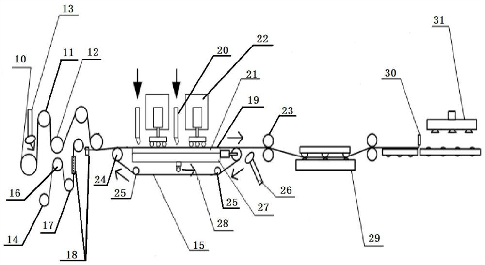
[0055] Specific implementation mode one: as figure 1 , figure 2 , image 3 , Figure 4 with Figure 5 As shown, this embodiment includes a film material manufacturing process, a conductive composite film manufacturing process, a cutting operation, a standby diaphragm manufacturing process, and a lamination and interconnection process;

[0056] Film material production process: unwind the second adhesive film layer 4 and the back film layer 5 from their respective rolls, utilize the high surface energy of the second adhesive film layer 4 and the back film layer 5 and discharge part of the air between them And the process of forming a roll of film material that fits physically; in the first driving wheel 10 in this operation process, the first driving wheel 10 cooperates with a plurality of first tension wheels 12, and the second adhesive film and the back film are respectively separated from each other. The material roll enters the first driving wheel 10, and uses the high...

specific Embodiment approach 2

[0072] Specific implementation mode two: as figure 1 , figure 2 , image 3 , Figure 4 with Figure 5 As shown, this embodiment includes the front film layer 1, the first film layer 2, the battery layer and the conductive composite film, and the front film layer 1, the first film layer 2, the battery layer and the conductive composite film are arranged sequentially from top to bottom , the battery layer includes a plurality of battery sheets 3, and a plurality of battery sheets 3 are horizontally arranged between the first adhesive film layer 2 and the conductive composite film, and the conductive composite film includes a second adhesive film layer 4, a back film layer 5 and a metal wire 6. The metal wire 6, the second adhesive film layer 4 and the back film layer 5 are arranged sequentially from top to bottom to form a whole. The solar cell assembly is a dual-function assembly of photovoltaic power generation and building tiles. According to sample tests, the solar cell...

specific Embodiment approach 3

[0078] Specific embodiment three: This embodiment is a further limitation of specific embodiment one. The part above the battery layer is called the front film layer 1, and the lower surface of the front film layer 1 is bonded to the first adhesive film layer 2. The front film layer 1 It is modified to ensure sufficient bonding strength with the EVA film, and its outer surface is treated with anti-reflection texturing. The front film layer 1 is an ETFE diaphragm, a PVDF diaphragm or a FEP diaphragm. The ETFE diaphragm is an ethylene tetrafluoroethylene polymer diaphragm, the PVDF diaphragm is a polyvinylidene fluoride diaphragm, and the FEP diaphragm is a fluorinated ethylene propylene polymer diaphragm.

[0079] The front film layer 1 can also be selected: photovoltaic glass; or organic polymer films such as PVDF and FEP;

[0080] The first adhesive film layer 2 is also optional: replace EVA with transparent polymer films such as PO, PA, PE, PET.


PUM

PropertyMeasurementUnit
thicknessaaaaaaaaaa
diameteraaaaaaaaaa
conversion efficiencyaaaaaaaaaa

Abstract

The invention discloses a solar battery interconnection manufacturing method and a solar battery assembly manufactured therewith. The manufacturing process of the existing silicon solar modules is complicated, the packaging cost is high, the operation is complicated, and the reliability is poor. The interconnection manufacturing method described in the present invention is to make the film material and carry out the conductive composite treatment, and the conductive composite film formed through the conductive composite treatment is laminated and interconnected with the diaphragm to be used to form a solar cell assembly; the solar cell assembly in the present invention includes The front film layer, the first adhesive film layer, the battery layer and the conductive composite film are integrally formed. The interconnection manufacturing method in the present invention is easy to operate, the overall structure of the manufactured solar battery module is simple and reasonable, and the packaging is stable and reliable.

Description

Technical field: [0001] The invention specifically relates to a solar cell interconnection manufacturing method and a solar cell module manufactured therefor. Background technique: [0002] Photovoltaic solar energy is an important and one of the fastest growing renewable energy sources. In the past ten years, the conversion efficiency of crystalline silicon solar cells represented by PERC and black silicon technology has increased to more than 20%, and further improvement is very difficult. During this period, the cost of battery cells has also been greatly reduced, but this is mainly due to economies of scale. [0003] At present, in the cost structure of components, the cost of component packaging has exceeded the cost of cells. Further reducing the cost of module packaging has become the key to the levelized cost of photovoltaic solar power generation reaching or lower than grid parity in most areas of my country. [0004] In the past two decades, except for the impro...

Claims


Application Information

Patent Timeline
Patent Type & Authority Patents(China)
IPC IPC(8): H01L31/18H01L31/05H01L31/048
CPCY02E10/50Y02P70/50
Inventor 桂裕鹏桂江虹林芝青王维汉王益锋
Owner 湖北美格新能源科技有限公司
Learn More