
Plastic coating PVD technology and plastic coating structure

A plastic and coating technology, which is applied in metal material coating process, coating, sputtering coating, etc., can solve the problems of many types of chemical agents, high cost, and mass production restrictions, so as to reduce the dosage of chemical agents and improve Product production yield, the effect of reducing the production process

Inactive Publication Date: 2019-07-09
KUNSHAN ENIJOR ELECTRONICS CO LTD
View PDF0 Cites 0 Cited by
  • Summary
  • Abstract
  • Description
  • Claims
  • Application Information

AI Technical Summary

Problems solved by technology

However, due to the lack of processing procedures for plastic substrates in the physical vapor deposition process, the film layer formed by it is not enough to meet the requirements in terms of adhesion and bonding. Although this deficiency can be made up by adding a spray coating, the cost is high. It is difficult to promote the application
[0004] However, the traditional water electroplating electroless nickel process needs to go through the processes of hydrophilicity, roughening, neutralization, palladium water, degelling, and electroless nickel electroplating. Utilization and protection; Moreover, due to the existence of processes such as the chemical nickel layer in the structure, electroplating single-layer nickel or multi-layer nickel layer, and electroplating hexavalent chromium layer, not only nickel sensitivity exists, but hexavalent chromium is highly toxic and easy to cause cancer. The disadvantages of high sewage treatment costs, and the products cannot meet the requirements of the EU WEEE and ROHS directives, making it difficult to export, and the clean production of electroplating cannot be truly realized
[0005] If the alternative solution of combining spray paint coating with physical vapor deposition film layer is adopted, the cost of this solution is high, and mass production is limited accordingly

Method used


Image

  • Plastic coating PVD technology and plastic coating structure
  • Plastic coating PVD technology and plastic coating structure

Examples


Embodiment Construction

[0023] The present invention will be further described in detail below in conjunction with the embodiments and the accompanying drawings, but the embodiments of the present invention are not limited thereto.

[0024] specific example

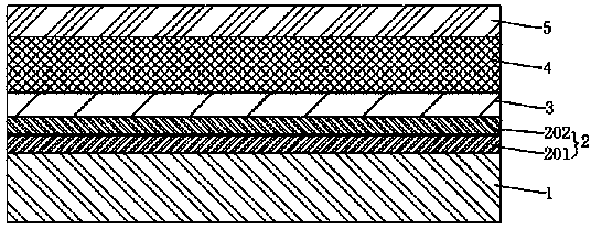
[0025] like figure 1 As shown, the present embodiment provides a plastic coating structure, which includes a plastic substrate 1, the plastic substrate 1 is covered with a physical vapor deposition metal film layer 2, and the physical vapor deposition metal film layer 2 is covered with a copper layer 3. The layer 3 is covered with a nickel layer 4, and the nickel layer 4 is covered with a chromium layer 5 and a chromium carbide layer.

[0026] Wherein, the physical vapor deposition metal film layer 2 includes a titanium metal layer 201 and a copper metal layer 202 , the titanium metal layer 201 covers the plastic substrate 1 , and the copper metal layer 202 covers the titanium metal layer 201 . By arranging the titanium metal layer on the phys...


PUM


Abstract

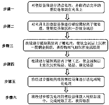
The invention discloses a plastic coating PVD technology. The plastic coating PVD technology comprises the steps that 1, surface cleaning treatment is conducted on a plastic substrate, and the cleanedplastic substrate is mounted on a clamp; 2, the plastic substrate on the clamp is subjected to magnetron sputtering ion plating treatment, and thus a titanium metal layer is deposited on the plasticsubstrate; 3, a magnetron sputtering ion plating technology is conducted, thus a copper metal layer, nickel layers, a chromium layer and a chromium carbide layer are deposited on the titanium metal layer in sequence; 4, the plastic substrate treated in the step 3 is activated or passivated; and 5, the plastic substrate treated in the step 4 is placed in pure chromium cylinder liquid to obtain thechromium layer. The metal film layer deposited through the plastic coating PVD technology meets the performance requirements of high adhesion, high binding force and good conductivity, and the productproduction yield is effectively increased.

Description

technical field [0001] The invention relates to the technical field of surface treatment of plastic shells of 3C electronic products, in particular to a PVD process for plating a metal layer on plastic parts and a coating structure thereof. Background technique [0002] With the rapid development of industry, covering the surface of plastic with metal not only increases the appearance, but also compensates for the shortcomings of plastic, endows the properties of metal, and gives full play to the characteristics of plastic and metal. Today, a large number of plastic electroplating products have been used in industries such as electronics, automobiles, and household products, and have become one of the important means of surface decoration in plastic products. At present, electroplating has been widely carried out on the surface of ABS, polypropylene, polysulfone, polycarbonate, nylon, phenolic glass fiber reinforced plastic, polystyrene and other plastics at home and abroad....

Claims


Application Information

Patent Timeline
Patent Type & Authority Applications(China)
IPC IPC(8): C23C14/35C23C14/20C23C14/16C23C14/06C23C28/00
CPCC23C14/0635C23C14/165C23C14/205C23C14/35C23C28/322C23C28/341
Inventor 蒋贵霞贾建国
Owner KUNSHAN ENIJOR ELECTRONICS CO LTD
Learn More