Distribution type biomass gasification poly-generation system and distribution type biomass gasification poly-generation method

A biomass and polygeneration technology, applied in the field of energy and environment, can solve the problems of waste heat resource waste, reduce thermal efficiency, etc., and achieve the effect of saving energy, reducing transportation costs, and achieving significant environmental benefits

Inactive Publication Date: 2019-08-30
KUNMING UNIV OF SCI & TECH
View PDF9 Cites 6 Cited by
  • Summary
  • Abstract
  • Description
  • Claims
  • Application Information

AI Technical Summary

Problems solved by technology

Organic Rankine cycle technology is an effective low-grade waste heat power generation technology, which has the advantages of low evaporation pressure and condensation pressure, high thermal efficiency and simple equipment, but the organic working medium still retains part of the heat energy after doing work in the steam turbine or expander. This part of heat energy is released by the condenser, and a large amount of condensation heat is not utilized and discharged into the environment, resulting in waste of waste heat resources and reducing the thermal efficiency of the system.

Method used


Image

  • Distribution type biomass gasification poly-generation system and distribution type biomass gasification poly-generation method

Examples


Embodiment 1

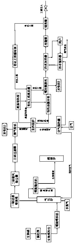
[0033] Embodiment 1: as figure 1 As shown, a distributed biomass gasification polygeneration system includes a biomass silo, a screw feeder, a fluidized bed gasifier, a combustion furnace, a screw conveyor, a gas turbine, a primary filter spray tower, a secondary Class cyclone dust collector, three-stage filter, waste heat boiler, air preheater, organic working medium evaporator, screw expander, hot water heater, hot water preheater, heat storage tank,

[0034] The outlet of the biomass silo is connected to the material inlet Ⅰ of the fluidized bed gasifier through the biomass conveying pipe Ⅰ, and the bottom discharge port of the fluidized bed gasifier is connected to the inlet of the screw conveyor through the biomass conveying pipe Ⅱ. The outlet of the screw conveyor returns to the bottom of the fluidized bed gasifier through the biomass delivery pipeline III, the outlet of the screw conveyor communicates with the bottom feed port of the combustion furnace through the bioma...

Embodiment 2

[0035] Embodiment 2: as figure 1 As shown, a distributed biomass gasification polygeneration system includes a biomass silo, a screw feeder, a fluidized bed gasifier, a combustion furnace, a screw conveyor, a gas turbine, a primary filter spray tower, a secondary Class cyclone dust collector, three-stage filter, waste heat boiler, air preheater, organic working medium evaporator, screw expander, hot water heater, hot water preheater, heat storage tank,

[0036] The outlet of the biomass silo is connected to the material inlet Ⅰ of the fluidized bed gasifier through the biomass conveying pipe Ⅰ, and the bottom discharge port of the fluidized bed gasifier is connected to the inlet of the screw conveyor through the biomass conveying pipe Ⅱ. The outlet of the screw conveyor returns to the bottom of the fluidized bed gasifier through the biomass delivery pipeline III, the outlet of the screw conveyor communicates with the bottom feed port of the combustion furnace through the bioma...

Embodiment 3

[0039] Embodiment 3: Distributed biomass gasification polygeneration method, adopting distributed biomass gasification polygeneration system (see figure 1 ),Specific steps are as follows:

[0040] (1) Biomass is added to the biomass silo after pretreatment, and the biomass in the biomass silo is fed into the fluidized bed gasifier through the screw feeder, and the air preheated by the air preheater is preheated The air delivery pipe leads into the fluidized bed gasifier to react with biomass to generate biomass charcoal and crude gas;

[0041] (2) Biomass charcoal in the fluidized bed gasifier enters the screw conveyor through the biomass conveying pipeline II, and the biochar used as the copper slag catalyst in the screw conveyor returns to the bottom of the fluidized bed gasifier, and the biochar in the screw conveyor The remaining biomass charcoal is transported to the combustion furnace for combustion through the biomass transportation pipeline IV;

[0042] (3) The crude...


PUM


Abstract

The invention relates to a distribution type biomass gasification poly-generation system and a distribution type biomass gasification poly-generation method, and belongs to the technical field of energy and environment. According to the method, biomass reacts with preheated air in a fluidized bed gasification furnace to generate biomass charcoal and crude fuel gas; the crude fuel gas is purified,and the purified crude fuel gas enters a fuel gas generator set to generate electricity; gas discharged from a gas turbine enters a waste heat boiler, and the residual heat of the flue gas is recovered and heats heat conduction oil; the heated heat conduction oil transfers the heat to an organic working substance; the organic working substance after endothermic vaporization drives a steam turbinegenerator set to generate electricity; after the work, the organic working substance enters a hot water heater, and heats preheated hot water; and then the organic working substance enters a condenser, and is converted into a liquid state so as to be recycled, and the medium-low temperature flue gas from the waste heat boiler is discharged by a chimney after the waste heat is recovered by an air preheater and a hot water preheater. According to the present invention, with the system and the method, biomass energy is converted into clean electric energy and high-quality biomass carbon to provide hot water for users so as to achieve the cascade utilization of biomass energy and improve the energy utilization.

Description

technical field [0001] The invention relates to a distributed biomass gasification polygeneration system and a method for cogeneration, belonging to the technical field of energy and environment. Background technique [0002] At present, my country is facing severe energy and environmental problems, and it is necessary to develop and utilize clean and non-polluting renewable energy with large resource reserves. At present, biomass energy is the only renewable carbon source. my country has abundant biomass energy resources and should be developed rationally. Utilizing biomass energy is one of the important ways to alleviate my country's energy crisis. The heat generated by the direct combustion of biomass can be directly supplied to users or used to produce steam, and then drive a turbogenerator to generate electricity. The advantage of this method is that the system is mature, but the efficiency is low. The main product of biomass gasification is combustible gas (the by-prod...

Claims


Application Information

Patent Timeline
Patent Type & Authority Applications(China)
IPC IPC(8): C10J3/54C10K1/02F01C1/16F01C13/00
CPCC10J3/54C10J2300/1615C10J2300/1675C10K1/024C10K1/026F01C1/16F01C13/00Y02P20/10Y02P20/129
Inventor 张舒雯刘慧利王亚思
Owner KUNMING UNIV OF SCI & TECH
Why Eureka
Try Eureka