Preparation and application of same-level rare earth luminescent probe based on luminescence lifetime change

A technology of rare earth luminescence and fluorescence lifetime, which is applied in the direction of luminescent materials, fluorescence/phosphorescence, nanotechnology for materials and surface science, etc. It can solve the problems of unrealized detection and achieve strong replaceability, high sensitivity, strong cosmetic effect

Active Publication Date: 2022-07-26
FUDAN UNIV
View PDF2 Cites 0 Cited by
  • Summary
  • Abstract
  • Description
  • Claims
  • Application Information

AI Technical Summary

Problems solved by technology

However, in this patent application, the rare earth nano-luminescent materials excited and emitted at the same energy level are only used in imaging and tracking, but do not respond to the external environment, nor can they detect in simple or complex environments.

Method used


Image

  • Preparation and application of same-level rare earth luminescent probe based on luminescence lifetime change
  • Preparation and application of same-level rare earth luminescent probe based on luminescence lifetime change
  • Preparation and application of same-level rare earth luminescent probe based on luminescence lifetime change

Examples


Embodiment 1

[0094] Example 1: Nanoparticle NaYF 4 : Synthesis of Tm

[0095] Take 0.99mmol of YCl 3 and 0.01 mmol of TmCl 3 The solid powder was added to a 100-mL three-necked flask containing 6 mL of oleic acid and 15 mL of octadecene, and an air-condensing device was built after adding a magnet and a thermometer. The temperature was raised to 110°C under nitrogen atmosphere, and then lowered to room temperature after the chloride was completely dissolved. While stirring, 10 mL of methanol solution prepared by dissolving 4 mmol of ammonium fluoride and 2.5 mmol of sodium hydroxide was added dropwise to the reaction flask, and the reaction solution gradually became cloudy. After stirring at room temperature for 15 minutes, the temperature was gradually increased to 110°C, and methanol was removed under a flowing nitrogen atmosphere. Then, after vacuuming to remove the remaining low-boiling substances, the temperature was rapidly raised to 300° C. for 1 hour under nitrogen atmosphere. ...

Embodiment 2

[0097] Example 2: Nanoparticle NaYF 4 :Yb, NaYF 4 :Nd, NaYF 4 : Synthesis of Er

[0098] NaYF 4 :Yb, NaYF 4 :Nd, NaYF 4 : Synthesis steps of Er nanoparticles and NaYF 4 : The synthesis of Tm nanoparticles is the same, in which TmCl 3 Replace solid powder with YbCl 3 , NdCl 3 or ErCl 3 .

[0099] figure 2 is NaYF in this example 4 : Transmission electron micrograph of the Yb luminescent probe, the material size is 10nm, the material has good dispersibility, and the particle size is uniform.

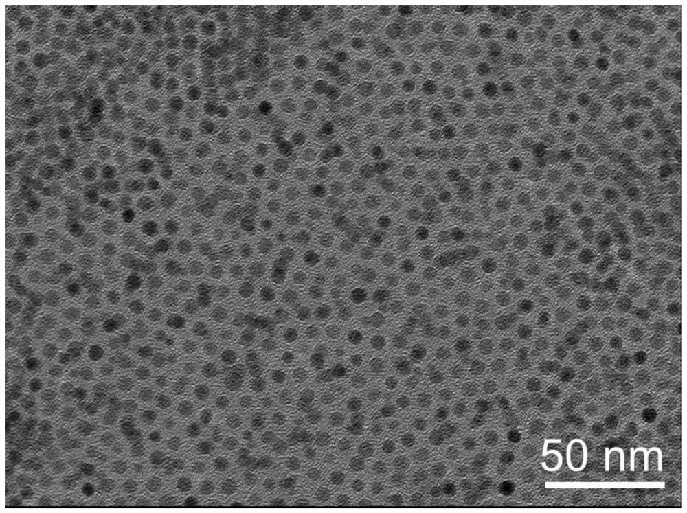
[0100] image 3 is NaYF in this example 4 : Transmission electron micrograph of the Nd light-emitting probe, the material size is 6.5nm, the material has good dispersion and uniform particle size.

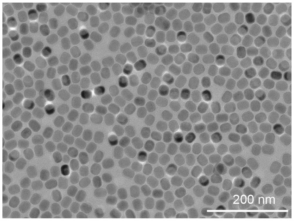
[0101] Figure 4 is NaYF in this example 4 : Transmission electron micrograph of the Er light-emitting probe, the material size is 38nm, the material has good dispersion and uniform particle size.

Embodiment 3

[0102] Example 3: Nanoparticle LiYF 4 :Nd, KYbF 3 , CaYbF 4 , BaYbF 4 Synthesis

[0103] LiYF 4 :Nd, KYbF 3 , CaYbF 4 , BaYbF 4 Synthetic steps of nanoparticles and NaYF 4 : The synthesis of Tm nanoparticles is the same, in which TmCl 3 Replace solid powder with YbCl 3 or NdCl 3, replace the NaOH solid with LiOH, KOH, Ca(OH) 2 or Ba(OH) 2 .

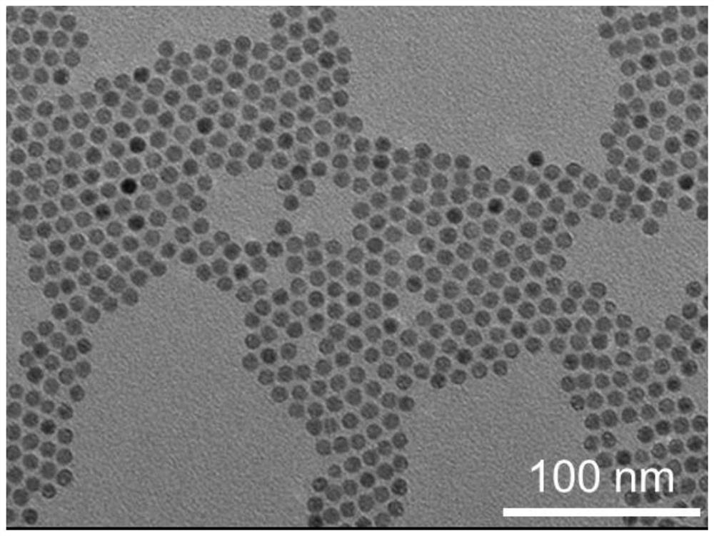
[0104] Figure 5 is LiYF in this example 4 : Transmission electron micrograph of the Nd luminescent probe, the material size is 31nm, the material has good dispersion and uniform particle size.

[0105] Image 6 is KYbF in this example 3 Transmission electron micrograph of the luminescent probe, the material size is 5nm, the material has good dispersibility, and the particle size is uniform.

[0106] Figure 7 is CaYbF in this example 4 Transmission electron micrograph of the luminescent probe, the size of the material is 10 nm, the material has good dispersibility, and the particle size is uniform.

[0107] Figure ...


PUM

PropertyMeasurementUnit
particle diameteraaaaaaaaaa
lengthaaaaaaaaaa

Abstract

The invention relates to the technical field of biological imaging, in particular to the preparation and application of a rare earth luminescence probe of the same energy level based on the change of luminescence lifetime. The rare earth luminescence lifetime probe comprises a luminescence donor Ln, an energy acceptor Qe, a linking material Link, the general structural formula is Ln‑Link‑Qe, and the luminescence donor is composed of rare earth nanoparticles (energy absorption and fluorescence emission occur in the same electronic state energy) grade) composition; the energy acceptor matches the luminescence band of rare earth nanoparticles, and the energy transfer process changes the fluorescence lifetime; the connecting material combines the luminescence donor and the energy acceptor through electrostatic adsorption, covalent coupling or entanglement to facilitate energy transfer. The luminescence process of the rare earth luminescent donor of the probe conforms to the first-order reaction kinetics, and the number of energy acceptors relative to the luminescent donor is linearly related to the fluorescence lifetime of the rare earth material, so that the lifetime signal can be used to realize the complex environment. It has great application prospects in the field of biological detection.

Description

technical field [0001] The invention relates to the technical field of biological imaging, in particular to the preparation and application of a rare earth luminescence probe of the same energy level based on the change of luminescence lifetime. Background technique [0002] Biological imaging technology has been widely used in many fields such as medical detection, including X-ray imaging, nuclear magnetic resonance imaging, fluorescence imaging and other technologies. Biological imaging technology has the advantages of non-invasiveness and intuitive results. Among them, fluorescence imaging technology occupies an important position in the field of biological imaging due to its advantages such as low cost, simple operation, and intuitive results. Therefore, a variety of fluorescent probes have been developed for fluorescence imaging tracking and detection in vivo and in vitro, such as organic dyes, inorganic quantum dots, carbon nanotubes, inorganic rare earth nanomaterials...

Claims


Application Information

Patent Timeline
Patent Type & Authority Patents(China)
IPC IPC(8): C09K11/85C09K11/02C09K11/06C09K11/61B82Y30/00B82Y40/00G01N21/64
CPCC09K11/7773C09K11/7705C09K11/02C09K11/06C09K11/616B82Y30/00B82Y40/00G01N21/6486G01N21/6428G01N2021/6432
Inventor 李富友孔梦涯顾昱飏吴娜冯玮
Owner FUDAN UNIV
Why Eureka
Try Eureka