
Shield slurry dewatering apparatus

A dehydration device and mud technology, applied in the direction of water/sludge/sewage treatment, water/sewage treatment, water/sewage multi-stage treatment, etc., can solve the problems of ignoring capillary water treatment, main engine wear, loud noise, etc., and achieve enhanced Improve the quality and efficiency of pore making, improve recycling and reduce environmental pollution

Pending Publication Date: 2019-11-08
HUNAN UNIV +1
View PDF0 Cites 4 Cited by
  • Summary
  • Abstract
  • Description
  • Claims
  • Application Information

AI Technical Summary

Problems solved by technology

Among them, the membrane filtration method is generally only suitable for mud with a solid content of less than 1.5%; the centrifugal method consumes a lot of energy and needs to add chemical flocculants, the noise is relatively large, the accessories are expensive, and it is difficult to repair; the screw pressure method has a small processing capacity and takes up a lot of space , the solid content after treatment is low, and the chemical flocculation dosage is large; the rotary extrusion method is only suitable for mud with high fiber content, good adaptability, low processing capacity, and high equipment cost
[0005] The supernatant of the above mechanical mud dehydration has a large solid content, which can easily cause blockage of the supernatant return pipe, and the main engine is severely worn. In the pipeline of the automatic flocculant dosing device, the agglomeration on the agitator and siltation, time-consuming and labor-intensive cleaning
At present, the electroosmotic dehydration technology is still immature, the energy consumption is relatively high, the solid content in the processing mud is required to be high (10-20%), the processing capacity is small, and the cost is high
[0006] In addition, in the existing treatment equipment, often only pay attention to the removal of free water in the mud, while ignoring the treatment of capillary water

Method used


Image

  • Shield slurry dewatering apparatus
  • Shield slurry dewatering apparatus
  • Shield slurry dewatering apparatus

Examples


Embodiment Construction

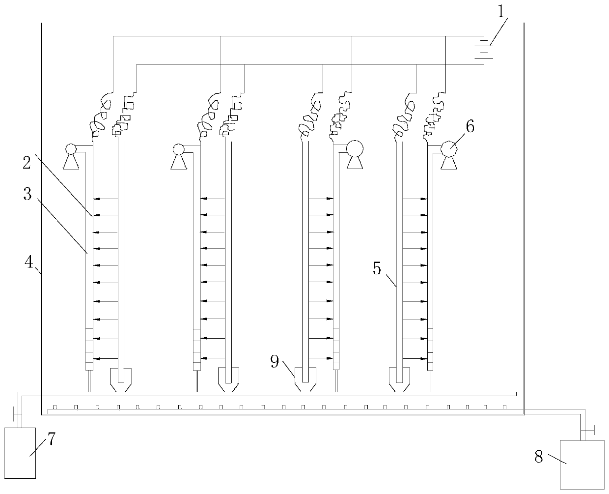
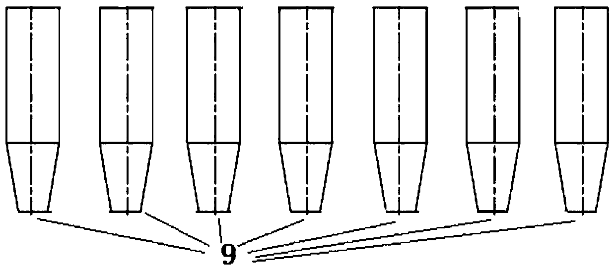
[0031] The present invention proposes a simple, effective, and low-cost shield mud dehydration device. The electrolysis-vacuum combined filtration mud dehydration is actually the separation of mud and water under the action of an electric field, and the obtained clarified filtrate is recycled. Therefore, the electrodialysis dehydration machine It mainly consists of a power supply 1, a cathode plate with holes 2 connected to the power supply 1, a flat ceramic membrane 3 adjacent to the cathode plate 2 with holes, a mud storage tank 4, an anode plate 5, a vacuum water collection device 6, a backwashing device 7, a blower Sweeping aeration device 8 and conical slot 9 for storing solid matter, the cathode plate with holes 2 is connected to the negative pole of the power supply 1, and the anode plate 5 is connected to the positive pole of the power supply 1; the flat ceramic membrane 3 and the cathode plate with holes 2 form together The cathode membrane, the upper end of the flat c...


PUM


Abstract

The invention relates to shield slurry dewatering apparatus. The apparatus comprises a power supply, perforated cathode plates connected with the power supply, flat ceramic membrane tightly adjacent to the perforated cathode plates, a slurry storage tank, anode plates, a vacuum water collecting device, a backwashing device, a purging aeration device and a conical clamping groove for storing solidmatter; each plate ceramic membrane and the corresponding perforated cathode plate together form a cathode membrane; the upper end of each plate ceramic membrane is connected with the vacuum water collecting device, wherein the vacuum water collecting device is used for collecting aggregated electrolytic clarified filtrates flowing in from the perforated cathode plates and the plate ceramic membranes during dewatering operation; the lower end of each plate ceramic membrane is connected with the backwashing device through a pipeline, wherein the backwashing device which is used for backwashingthe plate ceramic membranes to prevent soil particles from being blocked; and the bottom of the slurry storage tank is provided with the purging aeration device and the conical clamping groove for storing solid matter, wherein the conical clamping groove is used for collecting positive-ion soil particles accumulated near the anode plates during dewatering operation, and the purging aeration deviceis used for blowing high-pressure gas to stir slurry to roll. The slurry is stirred to roll, so that the flat ceramic membranes and the electrode plates are prevented from being polluted.

Description

technical field [0001] The invention relates to the field of mud dewatering, in particular to a shield mud dewatering device, which is mainly used for treating mud mud produced in the process of pipe jacking shield tunneling. Background technique [0002] In the construction of underground engineering, drilling piles, underground diaphragm walls, mud-water balance shield tunneling and other construction methods must use bentonite mud to support the tank walls and working faces. During the mud circulation, a large amount of Once the waste mud is not transported smoothly, it will affect the construction progress. Its composition and properties are different from municipal mud. It is a suspended liquid mainly composed of clay minerals and contains a certain amount of fine mud particles. The natural settlement and direct dehydration effect is poor. If it is not handled properly, it is easy to cause environmental pollution, damage water quality, block municipal pipelines, etc. h...

Claims


Application Information

Patent Timeline
Patent Type & Authority Applications(China)
IPC IPC(8): C02F9/12
CPCC02F1/48C02F1/4693
Inventor 卿启湘文桂林杨兴发曾嵘
Owner HUNAN UNIV
Features
  • Generate Ideas
  • Intellectual Property
  • Life Sciences
  • Materials
  • Tech Scout
  • Unparalleled Data Quality
  • Higher Quality Content
  • 60% Fewer Hallucinations
Learn More