A plasma jet device

A plasma and jet device technology, applied in the field of plasma, can solve the problems of lack of external connection protection and insulation device, no heat dissipation structure, difficult to use in practice, etc. The effect of ablation

Active Publication Date: 2020-09-15
NANJING UNIV OF AERONAUTICS & ASTRONAUTICS
View PDF2 Cites 0 Cited by
  • Summary
  • Abstract
  • Description
  • Claims
  • Application Information

AI Technical Summary

Problems solved by technology

The device has a simple structure and is easy to process and manufacture, but it is difficult to put into practical use because the discharge anode is used as the main body of the Laval nozzle and lacks external connection protection and insulation devices
At the same time, its working power is as high as 30kW, and neither the anode nor the cathode has a good heat dissipation structure, so the heat is serious
[0008] Through the above analysis, it can be seen that the existing supersonic plasma jet technology faces problems such as high power consumption, severe heat generation and ablation.

Method used


Image

  • A plasma jet device
  • A plasma jet device
  • A plasma jet device

Examples


Embodiment 1

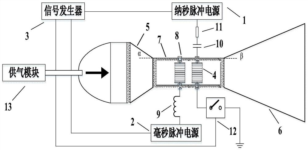
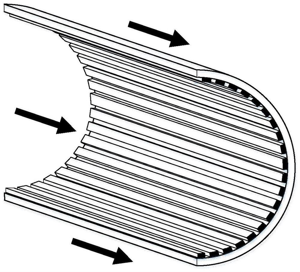
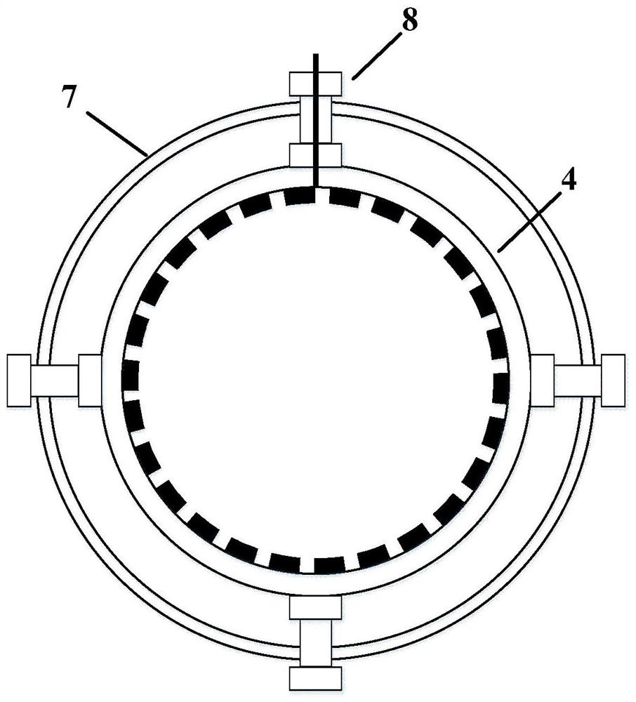
[0033] A plasma jet device such as figure 1 As shown, it includes nanosecond pulse power supply 1, millisecond pulse electric block 2, signal generator 3, toothed ring electrode 4, Laval nozzle contraction section 5, Laval nozzle expansion section 6, Laval nozzle throat 7 , flange 8, inductor 9, capacitor 10, resistor 11, high-voltage solid state switch module 12 and gas supply module 13. Among them, the schematic diagram of the toothed ring electrode and the cross-sectional view of the Laval nozzle throat are respectively shown in figure 2 and image 3 shown. Both ends of the throat of the Laval nozzle are provided with threads, and the contraction section of the Laval nozzle and the expansion section of the Laval nozzle are provided with threads that match the threads of the throat of the Laval nozzle, so as to realize the connection between the three. Connection.

[0034] In this embodiment, argon is selected as the working gas, and the gas flow rate is set to 50 L / min...

Embodiment 2

[0039] In this example, nitrogen is selected as the working gas, the gas flow rate is set to 100 L / min, and other devices are the same as those in Embodiment 1.

[0040] In this embodiment, the plasma jet generation process:

[0041] The control signal timing diagram is as follows Figure 5 As shown, adjust the pulse trigger signal through the signal generator to set the nanosecond pulse power supply to output pulse voltage in the form of pulse train, the frequency is 1kHz, the single pulse width is 200ns, the number of single-cycle pulses is 5, and the pulse interval time is 2μs. Set the trigger signal frequency of the high-voltage solid-state switch to 1kHz, turn on the solid-state switch 2 μs ahead of the nanosecond pulse power supply in timing, and close the solid-state switch with a delay of 2 μs after the end of the pulse train. After a delay of 2μs after the solid-state switch is closed, the millisecond pulse power supply outputs a pulse voltage with a frequency of 1kH...


PUM


Abstract

The invention discloses a plasma jet device, which comprises a nanosecond pulse power supply, a millisecond pulse power supply, a signal generator, a pair of annular electrodes, a Laval nozzle, a high-voltage solid-state switch module, a resistor, a capacitor, an inductance and a gas supply module. The Laval nozzle includes nozzle constriction section, nozzle throat and nozzle expansion section which are connected in sequence from end to end. A pair of ring electrodes are fixed inside the nozzle throat. There is a gap, the inner wall of the ring electrode is toothed, and the teeth on the two ring electrodes are staggered from each other. The invention not only reduces the operating voltage and power consumption of the plasma jet, but also improves the energy utilization efficiency and heat dissipation performance, and reduces the working temperature of the jet tube through the rational design of the electrode and the Laval nozzle and the timing coordination of the double pulse power supply system. Extended service life.

Description

technical field [0001] The invention belongs to the field of plasma technology, and in particular relates to a plasma jet device. Background technique [0002] Plasma is the fourth state of matter, which is composed of a large number of positive and negative charged particles and neutral particles, and exhibits collective behavior as a neutral aggregate. According to the degree of ionization, it can be divided into high-temperature plasma and low-temperature plasma. [0003] Atmospheric pressure low-temperature plasma jet generator is a new atmospheric pressure low-temperature plasma discharge technology that has emerged in recent years. The plasma generated in the discharge area is ejected from the nozzle or orifice by using the action of air flow and electric field. In the external gas environment, the plasma jet is formed by directional flow towards the working area. Atmospheric pressure low-temperature plasma jet source has the characteristics of simple structure, stab...

Claims


Application Information

Patent Timeline
Patent Type & Authority Patents(China)
IPC IPC(8): H05H1/34H05H1/36
CPCH05H1/34H05H1/36H05H1/3484H05H1/3494
Inventor 吴淑群刘雪原刘敏格杨璐张潮海
Owner NANJING UNIV OF AERONAUTICS & ASTRONAUTICS
Why Eureka
Try Eureka