
Membrane and electrochemical device comprising same

A diaphragm, electrostatic self-assembly technology, applied in electrochemical generators, circuits, electrical components, etc., can solve the problems of accelerating the flow rate of electrolyte, loss of energy, accelerating infiltration of electrolyte, etc., to improve cycle performance and energy density, The effect of prolonging the cycle life and shortening the rest time

Pending Publication Date: 2020-06-02
SHANGHAI ENERGY NEW MATERIALS TECH CO LTD
View PDF11 Cites 6 Cited by
  • Summary
  • Abstract
  • Description
  • Claims
  • Application Information

AI Technical Summary

Problems solved by technology

Most lithium-ion battery manufacturers speed up the infiltration by continuously optimizing the standing conditions after liquid injection, such as placing the cells horizontally, prolonging the standing time, increasing the standing temperature, etc., but these cannot fundamentally solve the problem of electrolyte infiltration inside the battery. The problem of slowness, because the electrolyte does not have enough channels to flow inside the battery, it is necessary to find a way to set up more channels inside the battery, on the one hand, to speed up the flow of the electrolyte, and on the other hand, it can accommodate more electrolyte
[0003] In order to solve this problem from the root, some people reduce the compaction density of the pole piece, which reduces the capacity of the battery and cannot meet the requirements of high energy density.
There are also people who treat the positive and negative electrodes, such as corona, to increase the surface roughness and gaps of the electrodes, and to speed up the infiltration of the electrolyte. This method not only loses part of the energy, but also affects the battery interface, which will lead to battery failure. Deformation of pole pieces during long-term charging and discharging, which increases safety risks

Method used


Image

  • Membrane and electrochemical device comprising same
  • Membrane and electrochemical device comprising same
  • Membrane and electrochemical device comprising same

Examples


Embodiment 1

[0083] The process of positive electrode sheet, negative electrode sheet, electrolyte, cell forming and so on is as follows:

[0084] Preparation of positive electrode sheet: Add lithium cobaltate, conductive carbon, and binder polyvinylidene fluoride into nitrogen methyl pyrrolidone (NMP) at a mass ratio of 97:1.5:1.5 and mix evenly to make positive electrode slurry, and then coat, Compacting and slitting to make positive electrode sheets.

[0085] Preparation of the negative electrode sheet: add graphite, conductive carbon, thickener sodium carboxymethyl cellulose, and binder styrene-butadiene rubber into deionized water at a mass ratio of 97:0.8:0.7:1.5 and mix them uniformly to form a negative electrode slurry, and then After coating, compacting and slitting, the negative electrode sheet is made.

[0086] Preparation of non-aqueous electrolyte: LiPF6, ethylene carbonate (EC) and diethyl carbonate (DEC) are configured into a solution with a LiPF6 concentration of 1.0mol / L ...

Embodiment 2

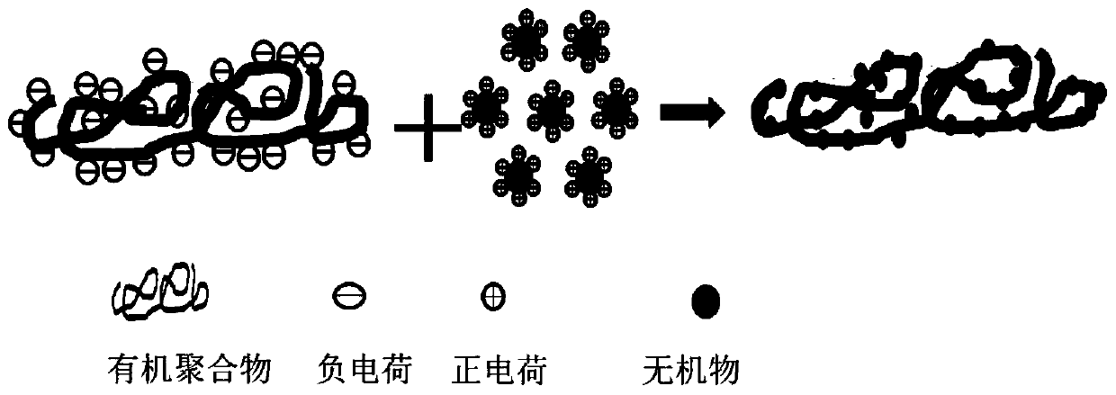
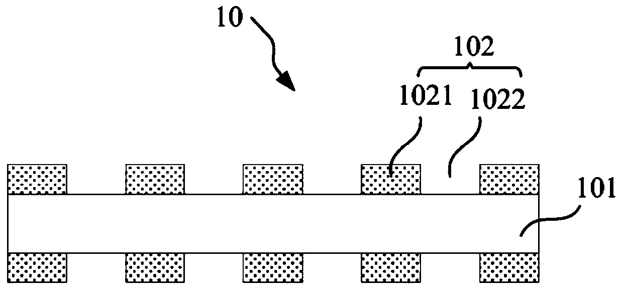
[0090] The processes of positive electrode sheet, negative electrode sheet, electrolyte solution, and cell molding are the same as in Example 1. The separator is as follows: the substrate is a 12 μm single-layer porous polyethylene substrate, and a discontinuous mixed coating with a thickness of 2 μm is provided on one side. A continuous mixed coating with a thickness of 2 μm is provided on one side, and the ceramic slurry in the coating film area includes the following mass components: 100 parts of polymethacrylic resin, lithium lanthanum titanium oxide Li x La 2 / 3-x TiO 3 (0﹤X﹤0.16) 5 parts, 100 parts of carbon disulfide, 0.5 part of sodium polystyrene sulfonate, 0.5 part of cetyltrimethylammonium bromide. Polymethacrylic acid resin was dispersed in carbon disulfide, and sodium polystyrene sulfonate was added to adjust the Zeta potential of the mixed system to below -30mV. lithium lanthanum titanyl Li x La 2 / 3-x TiO 3 (0﹤X﹤0.16) is dispersed in carbon disulfide, and the...

Embodiment 3

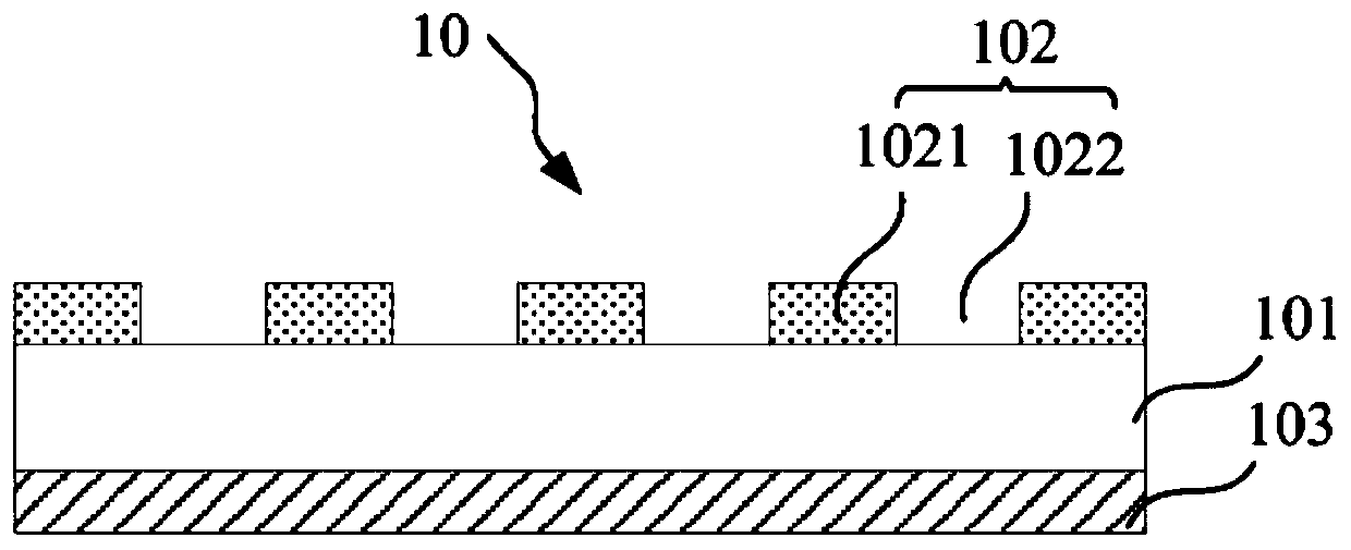
[0092] The processes of positive electrode sheet, negative electrode sheet, electrolyte solution, and cell molding are the same as in Example 1. The separator is as follows: the substrate is a 12um single-layer porous polypropylene substrate, and a continuous mixed coating with a thickness of 2μm is provided on both sides. One side of the coating is further provided with a discontinuous mixed coating with a thickness of 2 μm. The mixed coating ceramic slurry includes the following mass components: 100 parts of polyolefin, 5 parts of lithium aluminum oxide, 100 parts of acetone, poly 0.5 part of sodium styrene sulfonate, 0.2 part of cetyltrimethylammonium bromide. Polyolefin was dispersed in acetone, and sodium polystyrene sulfonate was added to adjust the Zeta potential of the mixed system to below -30mV. Lithium aluminum oxide was dispersed in acetone, and a cationic surfactant, cetyltrimethylammonium bromide, was added to adjust the Zeta potential of the mixed system to abov...


PUM

PropertyMeasurementUnit
Thicknessaaaaaaaaaa
Thicknessaaaaaaaaaa

Abstract

The present invention relates to a membrane and an electrochemical device comprising the same. The membrane is characterized in that the membrane at least comprises a porous substrate and a discontinuous adhesive layer provided on at least one side surface of the porous substrate; the non-continuous bonding layer comprises a coating area and a blank area; and the coating area contains slurry of acompound formed by electrostatic self-assembly of organic matters and inorganic matters. The blank area provides a channel for electrolyte infiltration of the electrochemical device, so the infiltration of the electrolyte can be accelerated, the electrolyte injection time and the standing time of the battery are shortened, the electrolyte retention amount of the battery is increased, and the cyclic service life of the battery is prolonged; and the non-continuous bonding layer of the isolating membrane has a bonding effect, so the porous substrate can be bonded with the positive electrode and the negative electrode to form a good interface, the deformation of the battery in the use process is prevented, the complete risk is reduced, and the cycle performance and the energy density are improved.

Description

technical field [0001] The invention relates to the technical field of lithium batteries, in particular to a diaphragm and an electrochemical device comprising the diaphragm. Background technique [0002] Power batteries, consumer electronics and energy storage fields have higher and higher requirements on the cycle life of chemical devices such as lithium-ion batteries, and longer cycle life requires more electrolyte retention. One of the current technical difficulties in increasing the electrolyte retention of lithium-ion batteries is how to speed up the infiltration speed of the electrolyte, so that more electrolyte can be injected within a certain period of time. Lithium-ion battery manufacturers mostly speed up the infiltration by continuously optimizing the standing conditions after liquid injection, such as placing the cells horizontally, prolonging the standing time, increasing the standing temperature, etc., but these cannot fundamentally solve the problem of electr...

Claims


Application Information

Patent Timeline
IPC IPC(8): H01M2/16H01M2/14H01M10/0525H01M50/403H01M50/417H01M50/446H01M50/449
CPCH01M10/0525H01M50/446H01M50/403H01M50/411H01M50/449Y02E60/10
Inventor 程跃王中奇陈永乐何方波鲍晋珍
Owner SHANGHAI ENERGY NEW MATERIALS TECH CO LTD
Learn More