
System and method for disposing steel plant collected dust through chain plate type high-temperature reduction furnace

A reduction furnace and chain plate type technology is applied in the field of comprehensive utilization of solid waste in the metallurgical industry, which can solve the problems of high iron content, low production efficiency, low zinc recovery efficiency, etc., and achieves high lead and zinc concentration, fast reaction speed, reduction Efficient effect

Pending Publication Date: 2020-06-12
长沙中硅环保科技有限公司
View PDF13 Cites 1 Cited by
  • Summary
  • Abstract
  • Description
  • Claims
  • Application Information

AI Technical Summary

Problems solved by technology

[0004] Invention patent CN 106191453 B discloses a method for recovering zinc concentrate and potassium chloride by using dust from a rotary hearth furnace. In this method, the dust from a rotary hearth furnace is soaked in water first, and then pulped and leached. The final slurry is separated from solid and liquid, and the obtained solid is washed and dried. In this patent, the wet method is used to treat the dust of the rotary hearth furnace, which has low production efficiency and large wastewater discharge.
This method is low in zinc recovery efficiency, and the iron content in blast furnace ash and electric furnace ash is high, and the liquid phase in the kiln is large during calcination, which is easy to agglomerate, which seriously affects the production and operation of the rotary kiln.
[0006] The production efficiency of the above two methods is low, the energy consumption cost is high, and the zinc in the dust collection ash has not been effectively recovered, and secondary pollution is likely to occur during the recovery process

Method used


Image

  • System and method for disposing steel plant collected dust through chain plate type high-temperature reduction furnace
  • System and method for disposing steel plant collected dust through chain plate type high-temperature reduction furnace
  • System and method for disposing steel plant collected dust through chain plate type high-temperature reduction furnace

Examples


Embodiment Construction

[0080] In order to make the object, technical solution and advantages of the present invention clearer, the present invention will be further described in detail below in conjunction with the accompanying drawings and specific embodiments.

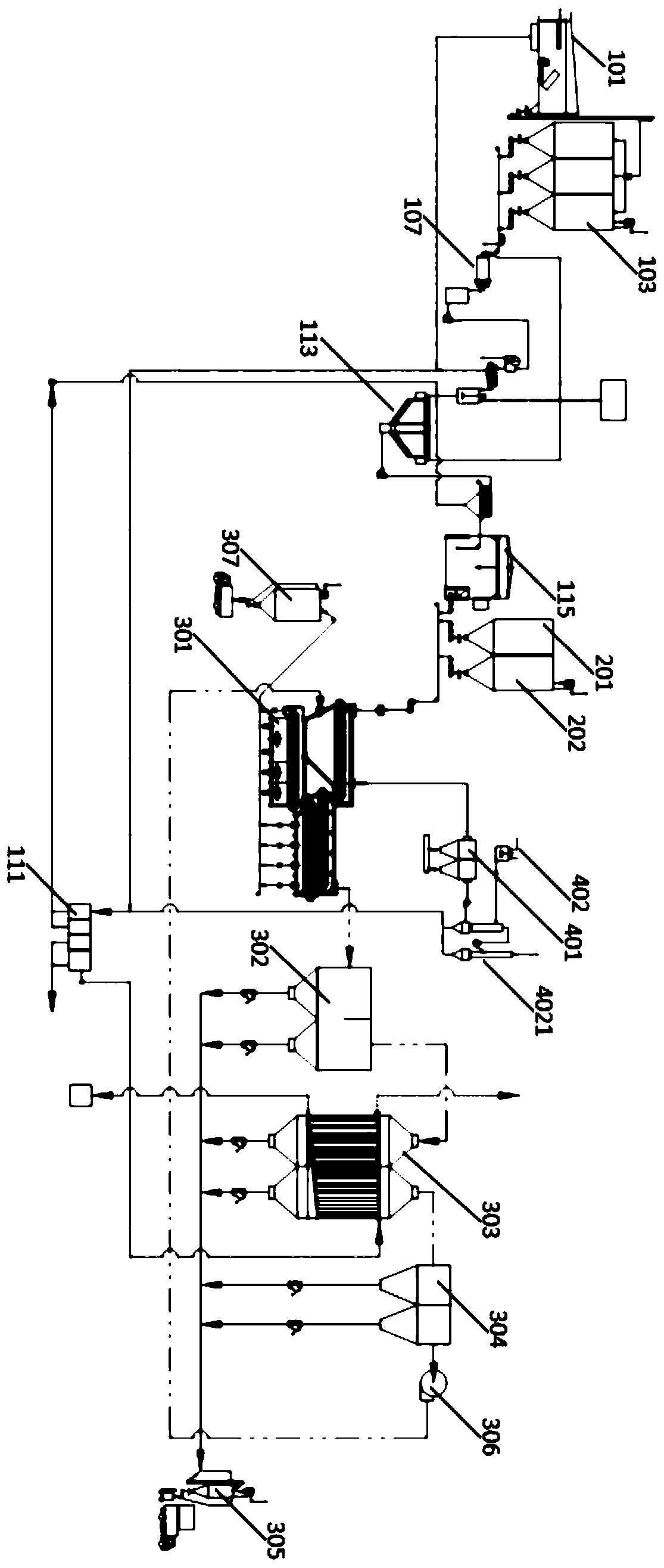
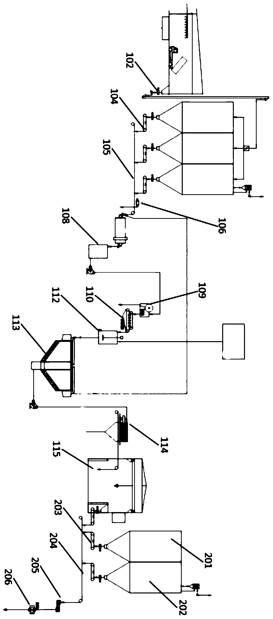
[0081] Such as Figure 1-7 As shown, this embodiment provides a chain-plate type high-temperature reduction furnace to dispose of dust collection system in iron and steel plant, including washing and dechlorination system, pelletizing system, volatile zinc extraction system and flue gas treatment system; wherein washing and dechlorination system, The granulation system is connected to the volatile zinc extraction system in sequence, and the flue gas treatment system is connected to the volatile zinc extraction system. The devices in the system are all sealed and equipped with a suction machine to form a slight negative pressure.

[0082] The washing and dechlorination system includes a discharge room 101, a plate feeder 102, a raw material...


PUM


Abstract

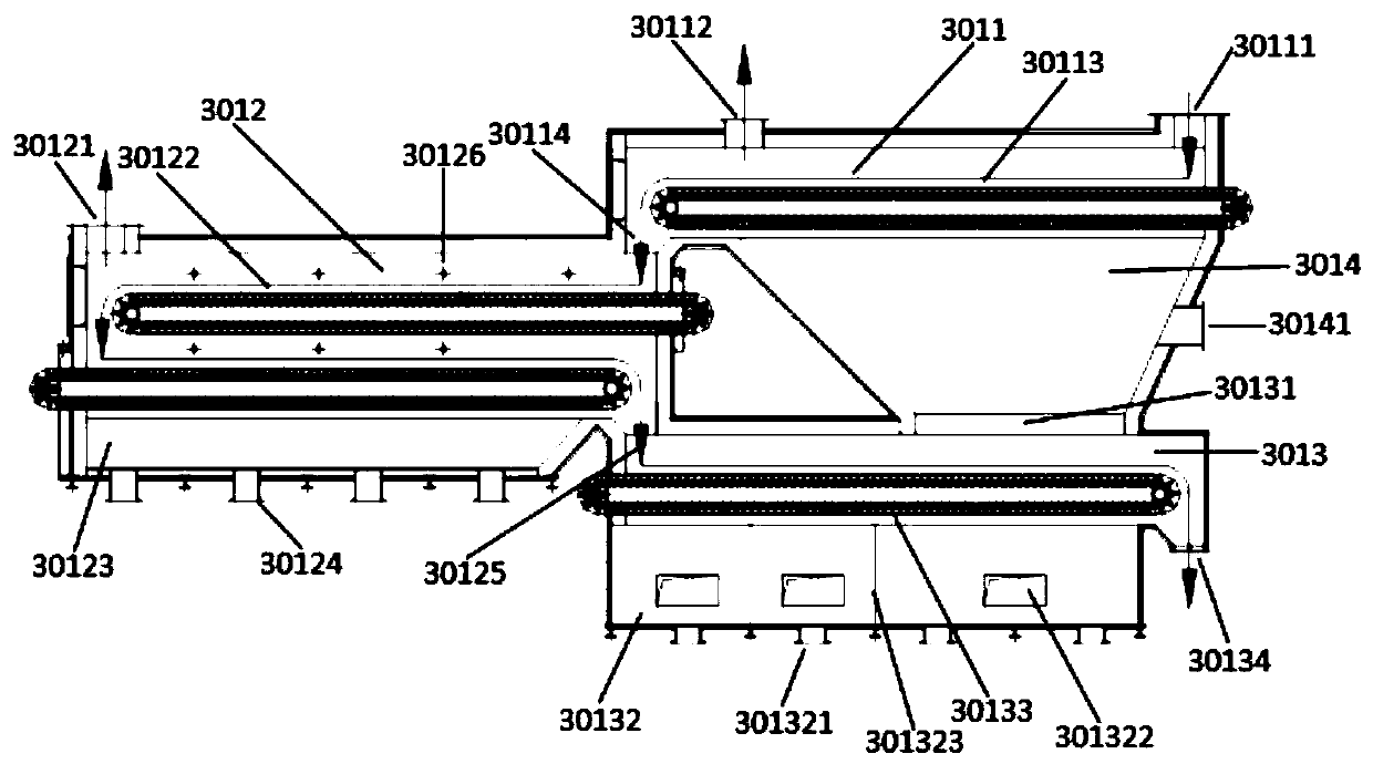
The invention discloses a system and method for disposing steel plant collected dust through a chain plate type high-temperature reduction furnace. The system comprises a washing dechlorination system, a pelletizing granulation system, a volatile zinc extraction system and a flue gas treatment system; and the volatile zinc extraction system comprises the chain plate type high-temperature reductionfurnace, an oxidizing chamber, a brine evaporation and flue gas settling machine, a high-temperature static dust collector and a solid storage which are connected in sequence, the high-temperature static dust collector is connected with the chain plate type high-temperature reduction furnace through an exhaust fan, the chain plate type high-temperature reduction furnace comprises a furnace body and a cavity wrapped with the furnace body, and the cavity is composed of an evaporation preheating part, a high-temperature reduction part and a cooling part. The chain plate type high-temperature reduction furnace is utilized as main incineration refining equipment, and the equipment is simple and unique in structure, convenient to operate and low in cost.

Description

technical field [0001] The invention belongs to the technical field of comprehensive utilization of solid waste in the metallurgical industry, in particular to a chain-plate type high-temperature reduction furnace disposal system and method for collecting dust in iron and steel plants. Background technique [0002] Dust collected by iron and steel plants includes blast furnace ash, converter ash and electric furnace ash produced by short-process enterprises. The waste production accounts for about 3%-5% of steel output. In 2017, my country's electric furnace steel production capacity reached 140 million tons, about Generate 2.8 million tons of electric furnace dust. The iron content of this dust collection ash usually reaches more than 35-55%. If it is directly returned to the blast furnace for use, zinc circulation and enrichment will occur in the blast furnace, which will endanger the production of the blast furnace; the zinc content in the dust collection dust is 5-30%, an...

Claims


Application Information

Patent Timeline
IPC IPC(8): C22B7/02C22B1/248C22B5/10C22B5/16C22B13/02C22B19/30C22B19/34B01D53/78B01D53/68B01D53/50C02F1/16B01D50/00
CPCC22B7/02C22B7/001C22B1/2406C22B1/248C22B5/10C22B5/16C22B13/025C22B19/30C22B19/34B01D53/78B01D53/68B01D53/507C02F1/16B01D50/00Y02P10/20
Inventor 肖喜才
Owner 长沙中硅环保科技有限公司
Learn More