Iron-nickel alloy in-situ desolventized layered perovskite cathode material for CO2 electrolysis

A technology of cathode materials and electrolyte materials, applied in the field of cathode materials for solid oxide electrolytic cells, can solve problems such as insufficient electrocatalytic activity, achieve the effects of improving electrocatalytic reduction activity, combining tightly, and increasing the concentration of oxygen vacancies

Active Publication Date: 2020-07-10
RES CENT FOR ECO ENVIRONMENTAL SCI THE CHINESE ACAD OF SCI
View PDF4 Cites 4 Cited by
  • Summary
  • Abstract
  • Description
  • Claims
  • Application Information

AI Technical Summary

Problems solved by technology

[0005] The purpose of the present invention is to overcome the perovskite-based cathode material to CO 2 The problem of insufficient electrocatalytic activity, in the perovskite Pr 0.5 Ba 0.5 MnO 3 The A site of the material introduces Pr and Ba vacancies, and the B site is doped with two transition metal ions, Fe and Ni. The molecular formula is Pr 0.45

Method used


Image

  • Iron-nickel alloy in-situ desolventized layered perovskite cathode material for CO2 electrolysis
  • Iron-nickel alloy in-situ desolventized layered perovskite cathode material for CO2 electrolysis
  • Iron-nickel alloy in-situ desolventized layered perovskite cathode material for CO2 electrolysis

Examples


Embodiment 1

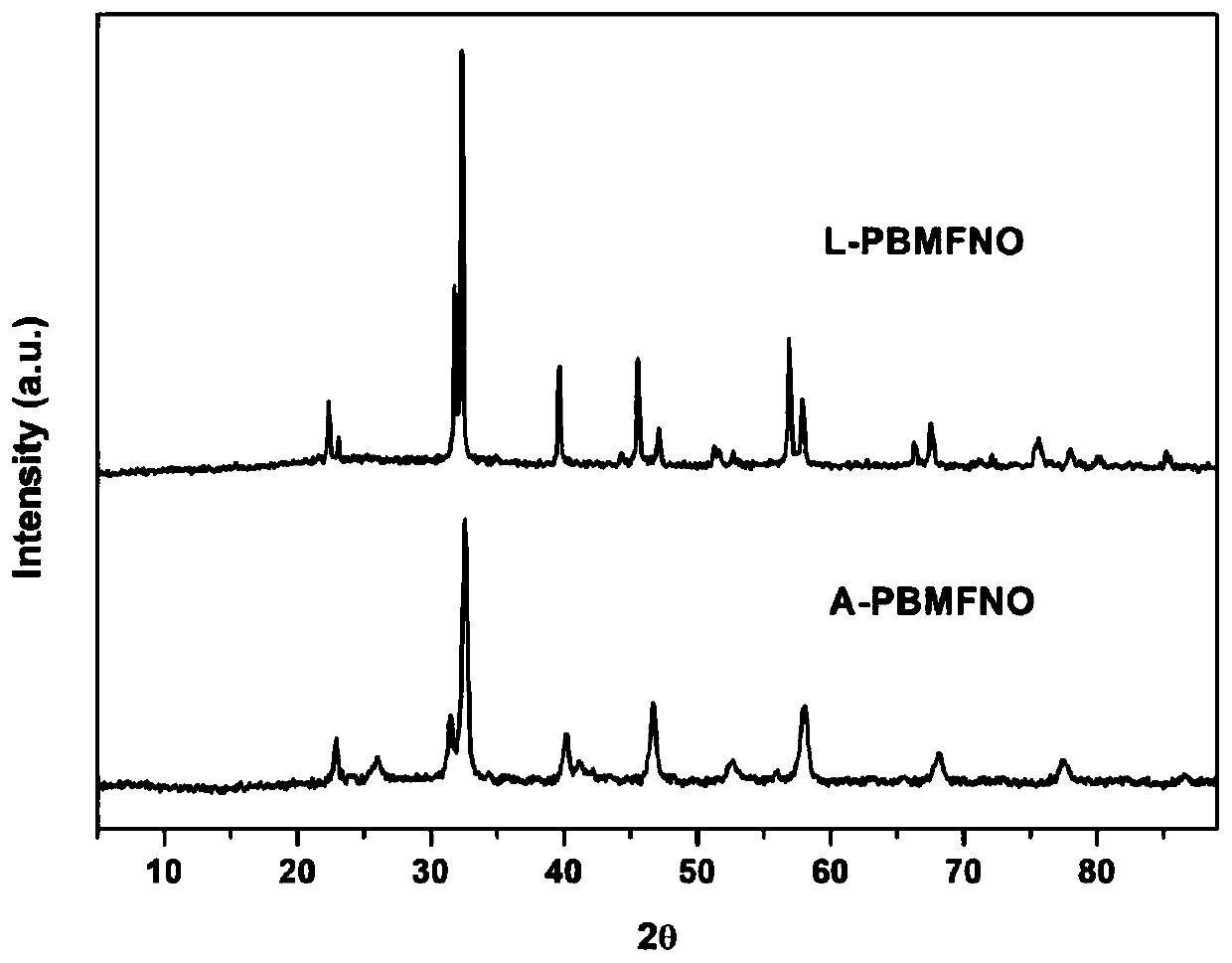
[0031] Step 1: According to Pr 0.45 Ba 0.45 Mn 0.5 Fe 0.4 Ni 0.1 O 3-δ The stoichiometric ratio of Pr, Ba, Mn, Fe and Ni in (A-PBMFNO) calculates the nitrate mass required by different elements. First dissolve these nitrates in deionized water, stir thoroughly for about half an hour, and then add 59.8899 g of citric acid monohydrate and 300 mL of ethylene glycol. At the same time, quickly adjust the pH of the solution to between 8-9 with ammonia water, and then continue to stir until a blood-red, clear and transparent precursor sol is formed. The speed of the magnetic stirrer is 400-500r / min, and the stirring time is 12h.

[0032] Step 2: The prepared precursor sol is transferred to the crucible, and a low-temperature self-propagating reaction is induced by heating by resistance wire. The temperature of the heater is controlled at 350°C, and the organic components, water, ammonia and other components in the precursor are gradually evaporated until a red-brown gel is formed. Aft...

Embodiment 2

[0038] Step 1: According to Pr 0.45 Ba 0.45 Mn 0.5 Fe 0.48 Ni 0.02 O 3-δ The stoichiometric ratio of Pr, Ba, Mn, Fe and Ni elements in the stoichiometric ratio respectively calculates the required nitrate mass of different elements. First dissolve these nitrates in deionized water, stir thoroughly for about half an hour, and then add 59.8899 g of citric acid monohydrate and 300 mL of ethylene glycol. At the same time, quickly adjust the pH of the solution to between 8-9 with ammonia water, and then continue to stir until a blood-red, clear and transparent precursor sol is formed. The speed of the magnetic stirrer is 400-500r / min, and the stirring time is 12h.

[0039] Step 2: The prepared precursor sol is transferred to the crucible, and a low-temperature self-propagating reaction is induced by heating by resistance wire. The temperature of the heater is controlled at 350°C, and the organic components, water, ammonia and other components in the precursor are gradually evaporated...


PUM

PropertyMeasurementUnit
Sizeaaaaaaaaaa

Abstract

The invention relates to a solid oxide electrolytic cell cathode material for CO2 electrolysis, in particular to an A-vacancy layered perovskite cathode material Pr0.9Ba0.9Mn<2-5x>Fe<4x>Ni<x>O<5+delta> (PBMFNO, x = 0.04-0.20) and an application thereof. The cathode material is characterized in that: Pr and Ba vacancies are introduced into an A site of a titanium ore material Pr0.5Ba0.5MnO3, two transition metal ions including Fe and Ni are doped into a B site, the molecular formula is Pr0.45Ba0.45Mn<1-5y>Fe<4y>Ni<y>O<3-delta> (y is equal to 0.02-0.10), Pr0.45Ba0.45Mn<1-5y>Fe<4y>Ni<y>O<3-delta>is converted into PBMFNO through H2 reduction, and meanwhile, iron-nickel alloy FeNi3 nanoparticles with the size of 30-50 nm are obtained through in-situ desolvation. The perovskite cathode materialprepared by the invention has good stability and CO2 catalytic activity, and can effectively reduce cathode polarization.

Description

Technical field [0001] The present invention relates to a method for CO 2 Solid oxide electrolytic cell (SOEC) cathode material for high-temperature electrolysis, specifically, a kind of Pr desolvated in situ from an iron-nickel alloy 0.9 Ba 0.9 Mn 2-5x Fe 4x Ni x O 5+σ (PBMFNO, x=0.04-0.20) A layered perovskite cathode material, and an SOEC cathode containing the cathode material. Background technique [0002] my country's energy structure has the characteristics of "lean oil, less gas, and rich coal". In recent years, the country has continuously promoted and supported the development of new coal chemical industries to ease the current situation of over-reliance on foreign oil and natural gas imports. At present, the new coal chemical industry technology continues to innovate and make breakthroughs, especially in the direct or indirect coal liquefaction, coal-to-liquid, natural gas, methanol and olefins, but a large amount of by-product CO 2 Bring a serious burden to the environ...

Claims


Application Information

Patent Timeline
IPC IPC(8): C25B11/06C25B1/00B22F9/22B22F1/00B01J23/00B01J23/889B01J35/00B82Y30/00
CPCC25B1/00B22F9/22B01J23/8892B01J23/002B01J35/0033B82Y30/00B01J2523/00C25B11/091B22F1/054B01J2523/25B01J2523/3718B01J2523/72B01J2523/842B01J2523/847
Inventor 朱建新乐王旭赵佳
Owner RES CENT FOR ECO ENVIRONMENTAL SCI THE CHINESE ACAD OF SCI
Why Eureka
Try Eureka