Device and method of recovering heat energy in waste water anaerobic treatment process

A technology for anaerobic treatment and recovery of heat energy, applied in anaerobic digestion treatment, combustion methods, waste fuels, etc., and can solve problems such as low energy utilization rate, corrosion of cylinder walls, equipment corrosion, etc.

Inactive Publication Date: 2020-08-14
SOUTH CHINA UNIV OF TECH
View PDF7 Cites 3 Cited by
  • Summary
  • Abstract
  • Description
  • Claims
  • Application Information

AI Technical Summary

Problems solved by technology

[0003] The existing energy recovery and utilization equipment from the anaerobic treatment process of wastewater is mainly biogas generators, but there are the following problems: (1) The operation stability is poor, and the existing biogas generators are mainly high-speed diesel generators with a power of more than 500kw The biogas flow and pressure generated by the common anaerobic tower are not enough to meet the operation requirements of the biogas generator. Once the biogas generated by the anaerobic treatment of wastewater is restricted by factors such as the influent flow, the concentration of organic pollutants, and the treatment effect, the biogas Fluctuations in production and pressure can easily lead to unstable operation or even shutdown of biogas generators
(2) The energy utilization rate is low. The chemical energy-electric energy conversion rate of the existing biogas generator does not exceed 30%. The biogas generator will release high-temperature exhaust gas, but the heat in the exhaust gas is difficult to recycle, resulting in a large amount of energy waste
(3) The equipment is severely corroded. Since the biogas contains impurities such as ammonia, hydrogen sulfide and phosphorus elements, when the biogas is burned in the cylinder of the generator, oxides of nitrogen, sulfur and phosphorus will be produced, and during the combustion of the biogas will produce A large number of water molecules, nitrogen, sulfur, phosphorus oxides combined with water molecules are strongly acidic, which will seriously corrode the cylinder wall and piston, causing them to rust, destroy the smoothness of the cylinder inner wall and piston surface, and easily cause piston lock to generate electricity machine parking
(4) Due to the poor combustion stability, it is easy to cause incomplete combustion of some components in the biogas, and it is easy to produce VOCs, nitrogen, phosphorus oxides and other pollutants, causing secondary pollution
(5) The structure of the generator is precise, the operation and maintenance management is difficult, and the failure rate is high, so it is not suitable for use in wastewater treatment stations or wastewater treatment plants with relatively harsh environments

Method used


Image

  • Device and method of recovering heat energy in waste water anaerobic treatment process
  • Device and method of recovering heat energy in waste water anaerobic treatment process
  • Device and method of recovering heat energy in waste water anaerobic treatment process

Examples


Embodiment 1

[0046] An anaerobic biogas thermal energy recovery project for a paper company that treats 5,000 tons of papermaking wastewater per day.

[0047] The Paper Co., Ltd. currently has two wastewater treatment anaerobic reaction towers with a diameter of 10 meters and a height of 20 meters, which can process 5,000 tons of papermaking wastewater every day. The two anaerobic towers together produce about 1,500 cubic meters of biogas per day.

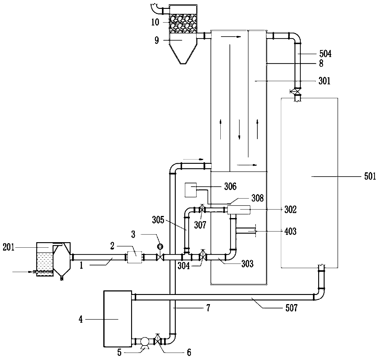
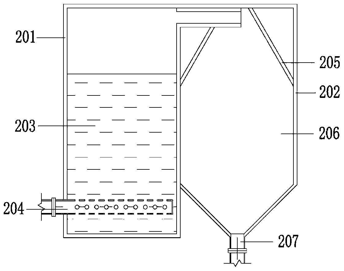
[0048] Such as figure 1 As shown, the heat recovery equipment used in this plant during the anaerobic treatment of wastewater includes a combustion heat exchanger body 8, a biogas purification system 201, a flame arrester 2, a gas pipeline 1, a heat transfer fluid storage tank 4, and a heat recovery utilization system 501. The combustion heat exchanger body 8 is a hollow cylinder structure with a height of 9 meters and a diameter of 2.5 meters. The combustion heat exchanger body 8 is provided with a gas delivery pipeline 303 and a control val...

Embodiment 2

[0058] A paper industry processes 3,000 tons of papermaking wastewater per day for an anaerobic biogas heat recovery project.

[0059] The difference between this embodiment and embodiment 1 is:

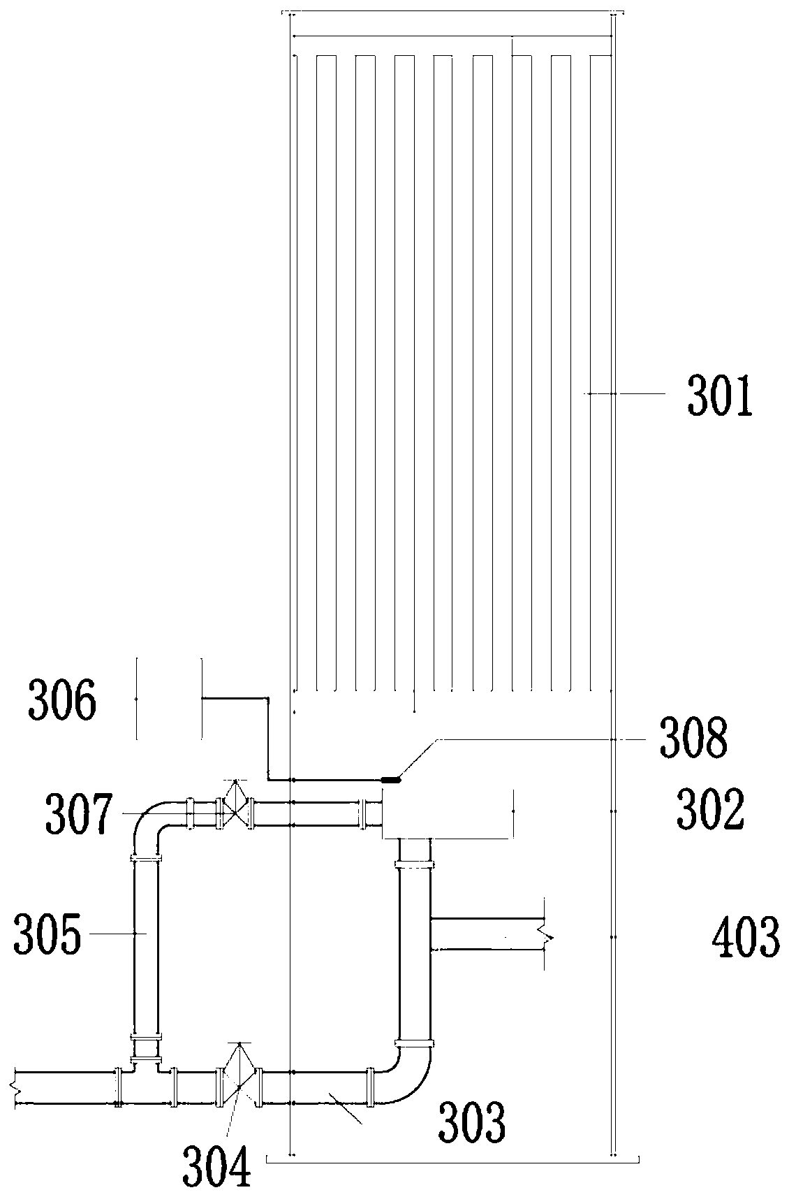
[0060] The combustion heat exchanger body 8 has an overall height of 10 meters and a diameter of 2.5 meters. The inner and upper thin-walled tubular heat exchanger system 301 adopts clustered thin-tube thin-walled heat exchange tubes with a diameter of 20 mm and a length of 5 meters. A total of 48; the surface of the stainless steel burner 302 is provided with 4 circles of circular pores according to concentric circles, and each circle has 8 circular pores with a diameter of 6 mm.

[0061] In this embodiment, the biogas generated by the anaerobic tower can increase the temperature of 10 tons of water by about 30°C per hour, and the heat production is equivalent to saving 0.6 tons of standard coal per day. The heated water enters the boiler to produce steam.


PUM

PropertyMeasurementUnit
angleaaaaaaaaaa
thicknessaaaaaaaaaa
heightaaaaaaaaaa

Abstract

The invention discloses a device and a method of recovering heat energy in a waste water anaerobic treatment process. Biogas is generated in waste water anaerobic treatment. Heat energy generated by combustion of biogas is transferred to a heat conducting fluid by means of a thin-walled tubular heat exchanger, and the heated heat conducting fluid heats a target according to a process demand, so that heat energy is recovered and utilized. According to the method, a combustion-supporting air/gas ratio and an air distributing pressure are set according to compositions of biogas, so that biogas iscombusted fully, and the emission amount of combusted tail gas is reduced. A thin-walled heat exchange tube system which is good in heat conducting property transfers heat to the heat conducting fluid efficiently, so that the comprehensive recycling ratio of heat energy of the waste water anaerobic fermentation product biogas reaches 80-90% which is far higher than 30% of biogas power generation.The method is suitable for recycling combustion heat energy of various organic waste water anaerobic fermentation products, has the advantages of being high in recycling ratio of heat energy, safe and easy to operate and small in tail gas pollutant emission, and has an application prospect in the field of recycling organic pollutant energy sources in waste water.

Description

technical field [0001] The invention belongs to the technical field of environmental protection and energy, and in particular relates to a device and method for recovering heat energy from wastewater anaerobic treatment process. Background technique [0002] With the rapid economic development and the country's increasing requirements for environmental governance, my country's wastewater treatment volume has increased year by year. In 2017, my country's wastewater treatment volume reached 46.549 billion cubic meters. Wastewater contains high concentrations of organic pollutants, and anaerobic biological treatment before conventional aerobic biochemical treatment has become a necessary part of the combined wastewater treatment process. After anaerobic fermentation of wastewater containing organic pollutants, a large amount of energy substances such as biogas whose main component is methane can be produced. Combustion and utilization of biogas generated during anaerobic treatm...

Claims


Application Information

Patent Timeline
Patent Type & Authority Applications(China)
IPC IPC(8): F23D14/02F23D14/60F28D7/08F28F21/08C02F3/28C10L3/10
CPCC02F3/28C10L3/103C10L3/104C10L3/105C10L3/106C10L2290/08F23D14/02F23D14/60F28D7/082F28F21/083Y02E50/30
Inventor 万金泉马邕文闫志成刘仰臣王艳
Owner SOUTH CHINA UNIV OF TECH
Why Eureka
Try Eureka