
Comprehensive treatment process of conversion condensate

A comprehensive treatment and condensate technology, applied in the field of coal chemical industry, can solve the problems of blocked pipes, low ammonia content, high sulfur content in ammonia water, etc.

Active Publication Date: 2020-10-30
WUHAN KELIN FINE CHEM
View PDF4 Cites 3 Cited by
  • Summary
  • Abstract
  • Description
  • Claims
  • Application Information

AI Technical Summary

Problems solved by technology

[0007] The purpose of the present invention is to achieve the purpose of processing and transforming the condensate through a reasonable process route, and recover the ammonia and sulfur in the condensate, so as to ensure that the ammonia water is qualified sulfur-free ammonia water, the ammonia content in the acid gas is low, and no clogging occurs , and can be sent to sulfur recovery to make sulfur, so as to solve the problems of acid gas with ammonia at the top of the tower blocking the pipeline and high sulfur content in ammonia water

Method used


Image

  • Comprehensive treatment process of conversion condensate
  • Comprehensive treatment process of conversion condensate

Examples

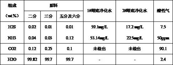

Embodiment 1

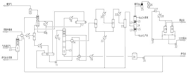
[0036] The comprehensive treatment process of transforming condensate in a chemical plant in Shanxi is as attached figure 1 As shown, its process includes the following steps:

[0037] Step 1: Transformation condensate comes from the liquid phase of the four separators in the conversion section, which are divided into two, three, five and six. First, after heat exchange, it is sent to the atmospheric stripping tower 1, and the steam is heated and stripped to maintain the pressure. 0.3MPa, the temperature at the bottom of the tower is 135°C, the liquid phase containing a small amount of ammonia at the bottom of the stripping tower is sent to gasification for reuse, and the gas phase at the top of the tower passes through the raw material water-atmospheric pressure stripping tower top gas heat exchanger 2. Atmospheric pressure stripping tower top After the cooler 3 is cooled, the liquid separation tank 4 at the top of the atmospheric stripping tower is separated, the gas phase o...

Embodiment 2

[0048] The comprehensive treatment process for transforming condensate in a chemical plant in Shandong is as attached figure 1 As shown, the shift condensate is first sent to the atmospheric stripping tower 1 after heat exchange, and is stripped by steam heating. The vaporized high-flash gas enters the middle and lower part of the deammonization tower as the stripping gas of the deammonization tower, and the pressure is maintained at 0.4MPa. The temperature at the bottom of the tower is 145°C, and the liquid phase containing a small amount of ammonia in the bottom of the stripping tower is sent to gasification for reuse, and the gas phase at the top of the tower passes through raw water-atmospheric pressure stripping tower top gas heat exchanger 2, atmospheric stripping tower top cooler 3 After cooling, the liquid separation tank 4 at the top of the atmospheric stripping tower is separated, the gas phase of the liquid separation tank is sent to the water washing tower 5, and th...


PUM


Abstract

The invention discloses a comprehensive treatment process of conversion condensate. The method comprises the following steps: firstly, removing NH3, H2S and CO2 in conversion condensate and gasified high-flash gas by using a normal-pressure stripping tower, cooling a top gas phase, feeding a liquid phase into a pressurizing stripping tower, by a single-tower pressurizing belt side line extractionprocess, mixing the top gas phase with a gas phase of a normal-pressure stripping tower after condensation and liquid separation, removing ammonia in the gas through a water washing tower, then removing and recovering sulfur, discharging or recycling purified water at the bottom after being cooled, and producing sulfur-free ammonia water with the mass concentration of 20% is produced after hydrogen sulfide is removed through a multi-effect acidic tail gas purifier after three-stage condensation and liquid separation are carried out on middle side extraction. The method has the advantages of reasonable process design, stable device operation and high added value of products, has huge environmental protection benefits, and solves the problems that the ammonia water treated by the conversioncondensate contains sulfur and acidic gas carries ammonia.

Description

technical field [0001] The invention belongs to the field of coal chemical industry and relates to a comprehensive treatment process for transforming condensate. Background technique [0002] In the coal-water slurry gasification and pulverized coal gasification process, the gasified crude gas enters the carbon monoxide conversion section, reacts with water vapor under a catalyst and a certain temperature, and generates carbon dioxide and hydrogen. Excessive steam is required in the carbon monoxide section, resulting in these Except for part of the water vapor participating in the reaction, most of the water vapor becomes a shift condensate after cooling. The main impurities are ammonia, hydrogen sulfide, carbon dioxide and some HCN, which are usually removed by steam stripping, and the purified condensate is sent back to the upstream gasification device for reuse. [0003] Domestically, the single-tower stripping or double-tower stripping process is adopted. In these two p...

Claims


Application Information

Patent Timeline
Patent Type & Authority Applications(China)
IPC IPC(8): C01C1/10C01C1/12C01B17/32C01B17/04C01B3/16C02F1/20C02F1/04B01D53/78B01D53/86B01D53/52C02F101/10C02F101/16
CPCB01D53/78B01D53/8612C01B3/16C01B17/04C01B17/32C01C1/10C01C1/12C02F1/04C02F1/20C02F2101/101C02F2101/16Y02P20/151
Inventor 李辉张先茂郭锐王瑜周庆国李琴李兴建夏克勤李青泽沈康文王利勇廖天泽
Owner WUHAN KELIN FINE CHEM
Learn More