
Naphtha hydrogenation micro-interface enhanced reaction system and method

A reaction system and hydrogenation reaction technology, applied in chemical instruments and methods, mixing methods, petroleum industry, etc., can solve the problems that hydrogen cannot fully contact with naphtha, high energy consumption, etc., and achieve low cost per ton of products, increase Effects of interphase area, enhanced mass transfer, and macroscopic reactions

Inactive Publication Date: 2021-01-05
NANJING YANCHANG REACTION TECH RES INST CO LTD
View PDF1 Cites 0 Cited by
  • Summary
  • Abstract
  • Description
  • Claims
  • Application Information

AI Technical Summary

Problems solved by technology

[0012] For this reason, the present invention provides a naphtha hydrogenation micro-interface strengthening reaction system and method to overcome the problem in the prior art that hydrogen gas cannot fully contact with naphtha, resulting in excessive energy consumption

Method used


Image

  • Naphtha hydrogenation micro-interface enhanced reaction system and method
  • Naphtha hydrogenation micro-interface enhanced reaction system and method
  • Naphtha hydrogenation micro-interface enhanced reaction system and method

Examples


Embodiment 1

[0106] In this embodiment, the standard volume ratio of hydrogen to naphtha in the first microinterface generator is 0.45:1; the standard volume ratio of hydrogen to naphtha in the microinterface generator is 450:1; the average diameter of the microbubbles Microbubbles greater than or equal to 1μm and less than 1mm; the air pressure inside the fixed reactor 4 is controlled at 0.7MPa; the reaction temperature is controlled at 275°C; the catalyst is iron-molybdenum catalyst; the space velocity is controlled at 5h -1 . Test results: the sulfur content in raw gasoline before treatment was 110ppm, and the sulfur content in treated naphtha dropped to 35ppm after treatment.

Embodiment 2

[0108] In this embodiment, the standard volume ratio of hydrogen to naphtha in the first microinterface generator is 0.20:1; the standard volume ratio of hydrogen to naphtha in the second microinterface generator is 400:1; Microbubbles with an average diameter greater than or equal to 1μm and less than 1mm; the air pressure inside the fixed reactor 4 is controlled at 1MPa; the reaction temperature is controlled at 280°C; the catalyst is iron-cobalt catalyst; the space velocity is controlled at 5.5h -1 . Test results: the sulfur content in raw gasoline before treatment was 110ppm, and the sulfur content in treated naphtha dropped to 43ppm after treatment.

Embodiment 3

[0110] In this embodiment, the standard volume ratio of hydrogen to naphtha in the first microinterface generator is 0.35:1; the standard volume ratio of hydrogen to naphtha in the second microinterface generator is 50:1; Microbubbles with an average diameter greater than or equal to 1 μm and less than 1 mm; the air pressure inside the fixed reactor 4 is controlled at 0.5 MPa; the reaction temperature is controlled at 270 ° C; the catalyst is a molybdenum-nickel catalyst; the space velocity is controlled at 4 hours -1 . Test results: the sulfur content in raw gasoline before treatment was 110ppm, and the sulfur content in treated naphtha dropped to 48ppm after treatment.


PUM

PropertyMeasurementUnit
kinematic viscosityaaaaaaaaaa
diameteraaaaaaaaaa

Abstract

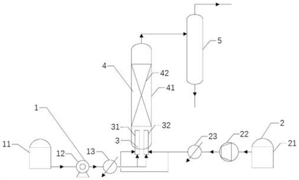
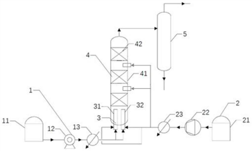
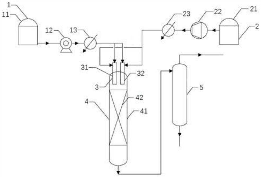
The invention relates to a naphtha hydrogenation micro-interface enhanced reaction system and method. The naphtha hydrogenation micro-interface enhanced reaction system comprises a liquid phase feeding unit, a gas phase feeding unit, a micro-interface generator, a fixed bed reactor and a separation tank. Compared with a traditional fixed bed reactor, the micro-interface generator is arranged on the fixed bed reactor, before reaction raw materials enter the reactor for reaction, pressure energy of gas and / or kinetic energy of liquid in the reaction process are / is converted into surface energy of hydrogen bubbles, hydrogen bubbles are crushed into micro-bubbles with a diameter of 1 [mu] m or more and less than 1 mm, such that the phase contact area of naphtha and hydrogen during a hydrogenation reaction process is effectively increased, the mass transfer efficiency between naphtha and hydrogen is improved, naphtha and hydrogen micro-bubbles are mixed after crushing so as to form a gas-liquid emulsion, and furthermore, the reaction efficiency between naphtha and hydrogen is enhanced within a relatively low preset pressure range.

Description

technical field [0001] The invention relates to the technical field of naphtha processing, in particular to a naphtha hydrogenation micro-interface strengthening reaction system and method. Background technique [0002] In recent years, with the increasing scarcity of oil resources, the trend of heavy and inferior crude oil has become increasingly serious, and with the development of the economy, the demand for light oil products is increasing. Therefore, the largest amount of heavy oil to light, Maximization of benefits has become the goal pursued by oil refineries. [0003] The main means of heavy oil processing are hydrocracking, catalytic cracking and delayed coking. The application of hydrocracking is limited due to large investment, high operating cost, difficulty in processing coker naphtha and residual oil, and the application of delayed coking is also limited due to factors such as low liquid yield and poor product quality. Catalytic cracking has low operating cos...

Claims


Application Information

Patent Timeline
Patent Type & Authority Applications(China)
IPC IPC(8): C10G45/22C10G45/72B01J8/02B01F3/04B01J8/00
CPCC10G45/22C10G45/72B01J8/0278B01J8/001C10G2300/1044C10G2300/202B01F23/2319B01F23/23764B01F23/2373
Inventor 张志炳周政孟为民王宝荣杨高东罗华勋张锋李磊杨国强田洪舟曹宇
Owner NANJING YANCHANG REACTION TECH RES INST CO LTD
Learn More