
Ultrasonic vibration machining device and method for aluminum-based silicon carbide composite material

An aluminum-based silicon carbide and ultrasonic vibration technology, which is applied to metal processing equipment, manufacturing tools, milling machine equipment details, etc., can solve problems such as affecting processing efficiency, low processing efficiency, and built-up edge

Active Publication Date: 2021-03-26
HENAN POLYTECHNIC UNIV
View PDF14 Cites 6 Cited by
  • Summary
  • Abstract
  • Description
  • Claims
  • Application Information

AI Technical Summary

Problems solved by technology

Ultrasonic vibration requires a small amplitude, which easily leads to low processing efficiency. For hard and brittle materials, the microscopic impact between the tool and the workpiece causes the tool to be chipped and damaged; laser heating can improve the plasticity of the material through laser heating, thereby increasing the material removal rate. Avoid cracks in the process of machining, reduce cutting force, and reduce tool wear, but it will lead to softening of the aluminum base, easy to produce built-up edge, and high temperature aluminum base softening will cover the surface of the material, affecting processing efficiency

Method used


Image

  • Ultrasonic vibration machining device and method for aluminum-based silicon carbide composite material
  • Ultrasonic vibration machining device and method for aluminum-based silicon carbide composite material
  • Ultrasonic vibration machining device and method for aluminum-based silicon carbide composite material

Examples


Embodiment Construction

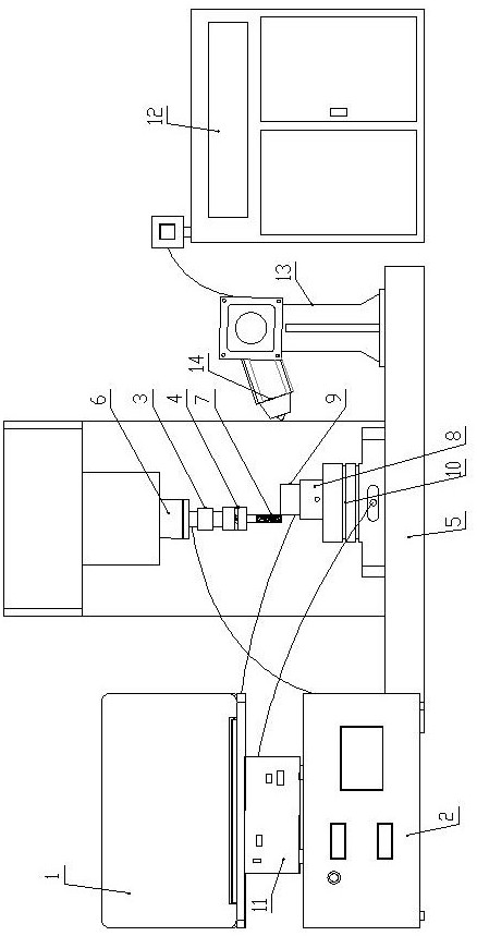
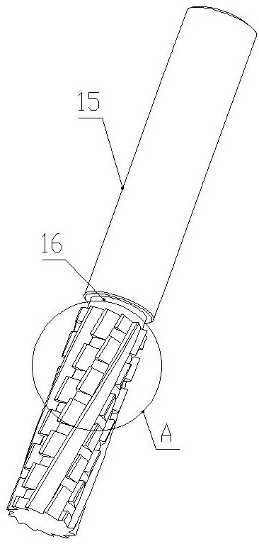
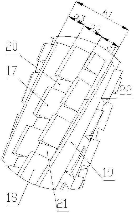
[0029] Such as Figure 1-Figure 5 As shown, an ultrasonic vibration processing device of the present invention for aluminum-based silicon carbide composite materials includes a computer 1, a laser-assisted heating part, an ultrasonic vibration processing part and a milling processing part;

[0030] The ultrasonic vibration processing part includes an ultrasonic generator 2, a transducer 3 and a horn 4; the horn 4 adopts an oblique beam type longitudinal-torsion compound ultrasonic vibration horn;

[0031] The milling processing part includes a machine tool table 5, a machine tool spindle 6 and a micro-blade milling cutter 7;

[0032] The machine tool spindle 6 is set vertically downward, the lower end of the machine tool spindle 6 is connected to the transducer 3, the lower end of the transducer 3 is connected to the horn 4, the upper end of the microblade milling cutter 7 is clamped at the lower end of the horn 4, and the ultrasonic generator 2 passes through the The wire is...


PUM


Abstract

The invention discloses an ultrasonic vibration machining device and method for an aluminum-based silicon carbide composite material. The ultrasonic vibration machining device comprises a computer, alaser auxiliary heating part, an ultrasonic vibration machining part, a machine tool workbench, a machine tool spindle and a micro-edge milling cutter, wherein the ultrasonic vibration machining partcomprises an ultrasonic generator, a transducer and an amplitude-change pole; the lower end of the machine tool spindle is connected with the transducer, the lower end of the transducer is connected with the amplitude-change pole, the upper end of the micro-edge milling cutter is clamped at the lower end of the amplitude-change pole, and the ultrasonic generator is connected with the transducer through a wire; a clamp holder is arranged on the machine tool workbench, a workpiece made of the aluminum-based silicon carbide composite material is clamped on the clamp holder, and the clamp holder is connected with a three-way dynamometer; and the laser auxiliary heating part is used for heating a to-be-machined part of the workpiece. In the milling operation process, chip removal can be accelerated, flutter of a cutter is eliminated, abrasive abrasion and adhesive abrasion are reduced, milling force and cutting heat are reduced, the machining size precision is guaranteed, the workpiece surface quality and the machining efficiency are improved, and the machining cost is saved.

Description

technical field [0001] The invention belongs to the technical field of precision ultra-precision machining, and in particular relates to an ultrasonic vibration machining device and method for aluminum-based silicon carbide composite materials. Background technique [0002] Aluminum-based silicon carbide composite materials have the characteristics of high specific strength, low thermal expansion coefficient, and good thermal stability, and are widely used in national defense, aerospace, electronics, and chemical industries. The hard phase silicon carbide particles are distributed in the aluminum matrix. The particles enhance the physical and mechanical properties of the material and increase its cutting processing difficulty, so that surface defects such as protrusions, cracks, and pits often occur during processing; appear on the edge of the workpiece Edge damage such as burrs, edge chipping, chipping and peeling, ordinary milling tools are easily worn by silicon carbide p...

Claims


Application Information

Patent Timeline
IPC IPC(8): B23C3/00B23C9/00
CPCB23C3/00B23C9/00
Inventor 向道辉彭培成李艳琴张晓辉雷小飞张志强赵波高国富焦锋童景琳
Owner HENAN POLYTECHNIC UNIV
Learn More