Method and apparatus for electrophoretically dyeing biological sample by using ion conductive film

An ion-conducting membrane and biological sample technology, which is applied in the preparation, sampling, and measurement devices of test samples, can solve the problems of deterioration of light scattering resolution, large numbers, and difficult internal tissue imaging, and achieve reproducible and effective staining. , High electrical efficiency, the effect of minimizing damage

Pending Publication Date: 2021-04-30
CRAYON TECH INC
View PDF0 Cites 0 Cited by
  • Summary
  • Abstract
  • Description
  • Claims
  • Application Information

AI Technical Summary

Problems solved by technology

[0002] When a thick biological tissue sample is observed with an optical device such as a microscope, there are problems in that severe light scattering occurs and the resolution deteriorates geometrically, so it is difficult to image the inner tissue of the thick biological tissue sample
Thus, methods using centrifugal force can move antibodies into relatively thick biological samples, but centrifugal force damages the tissue, thus limiting the ability to observe the shape of the original intact tissue
[0006] Third, as a technique for performing immunostaining by forming an electric field, there are limitations in efficiency and practicability: the highest resistance is applied to the center of the sphere due to a straight electric field, and thus antibody staining between the edge and the center have such large variances that uniform staining is impossible; nanoporous membranes are used to limit sample movement, but as staining progresses, antibody concentration decreases due to inflow into solution due to osmotic pressure; There are physical limitations when staining tissues of various shapes and sizes; since the pore size of commercially available nanoporous membranes is constant, staining components or buffer components with very small molecular weights flow out of the chamber; due to the nanopore The pore size of the membrane is not constant, so the reproducibility of staining is reduced; and a large number of immune antibodies must be used for a single staining

Method used


Image

  • Method and apparatus for electrophoretically dyeing biological sample by using ion conductive film
  • Method and apparatus for electrophoretically dyeing biological sample by using ion conductive film
  • Method and apparatus for electrophoretically dyeing biological sample by using ion conductive film

Examples


example 1

[0146] Example 1: Preparation of samples

[0147] The brains of non-transformed rats (SD rats, 4-6 weeks old) were used to prepare clear brain tissue samples by the typical CLARITY method.

[0148] Perfusion through the heart drains blood from the microvasculature of the brain. The brain was excised from the rat, immersed in the hydrogel monomer solution, and incubated at 4°C for 2 days, wherein, in the hydrogel monomer solution, 4% (w / v) acrylamide, 0.25% (w / v) VA-044, and 4% (w / v) PFA (paraformaldehyde) were dissolved in phosphate saline (PBS) solution.

[0149] Then, the brain was placed under vacuum for 2 to 4 hours in the dark, and the temperature was raised to 37°C by using a special machine (CLARITY Easy-Imbedding, LCI).

[0150]Thereafter, after cutting the brain into the desired sample size (thickness: 500 μm, 1 mm, 1.5 mm, 2 mm, 5 mm; diameter: 5 mm, 10 mm), electrical tissue was performed by using a CLARITY machine (CLARITY Easy-Clearing, LCI) Transparency (Ele...

example 2

[0152] Example 2: Biological samples using the electrophoresis method for staining biological samples with an applied ion-conducting membrane Preparation of dyeing equipment

[0153] The fabricated sample chamber is mounted between the respective electrode parts of a device comprising a power source, two electrode parts, a buffer supply part and a cooler, each electrode part including a lower buffer inlet on one side and a buffer inlet on the opposite side. The upper part of the buffer outlet, the buffer supply part (borate buffer; 50mM LiOH, 25mM boric acid) is connected to the buffer inlet and buffer outlet of the two electrode parts, and the cooler is connected to the buffer supply part . The device includes a cooling water circulation channel arranged to completely contact the two sides, the lower surface, and the upper surface of the sample chamber except the two sides in contact with the electrodes, and has a cooling water circulation channel through which the coolin...

example 3

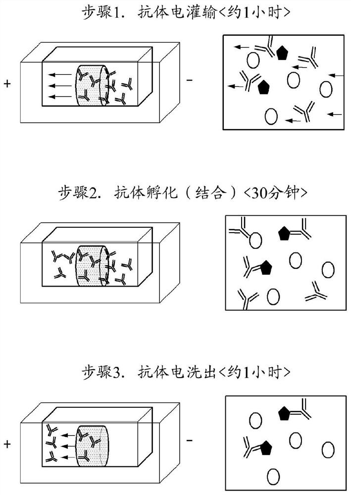
[0154] Example 3: Immunostaining test using ion-conducting membrane by electrophoretic technique (primary and secondary antibody detection test) - glial cell staining

[0155] CLARITY samples of brain fibers of untransformed rats (SD rats, 4-6 weeks old) obtained in Example 1 were immunized by electrophoresis using ion-conducting membranes using antibodies to glial fibrillary acidic protein (GFAP) Stain and then image.

[0156] The brain tissue sample prepared in Example 1 with a diameter of 10 mm and a thickness of 1 mm was inserted into the holder body of the sample chamber in the device prepared in Example 2, and inserted into the biological sample fixing part to be fixed, and then the electrode part and the sample Each space of the chamber was filled with borate buffer (50 mM LiOH, 25 mM boric acid). An antibody targeting GFAP (primary antibody, Abcam, UK) and an antibody targeting the Fc part of the primary antibody labeled with a fluorescent material (secondary anti...


PUM

PropertyMeasurementUnit
thicknessaaaaaaaaaa
thicknessaaaaaaaaaa
thicknessaaaaaaaaaa

Abstract

A method for dyeing a biological sample according to one embodiment of the present invention may comprise: a step for positioning a biological sample adjacent to a dyeing reagent for a biological sample, and separating the biological sample and the dyeing reagent for a biological sample from an external buffer by using an ion conductive film; and a step for forming an electric field such that an electric current flows through the ion conductive film to the dyeing reagent for a biological sample and the biological sample. Here, the biological sample is one that has been separated from a living body.

Description

technical field [0001] The present invention relates to a biological sample dyeing method and dyeing equipment, more particularly to a biological sample dyeing method and dyeing equipment using electrophoresis technology. Background technique [0002] When a thick biological tissue sample is observed with an optical device such as a microscope, there are problems in that severe light scattering occurs and resolution deteriorates geometrically, so it is difficult to image the inner tissue of the thick biological tissue sample. To overcome these limitations, tissue clearing techniques have been continuously investigated. [0003] Immunostaining is theoretically possible in transparent tissue through which fluorescent antibodies can pass due to the formation of large and small pores within it, but when typical immunostaining is performed by traditionally used passive diffusion method, immunostaining times increase exponentially with the thickness of clear tissue, making immuno...

Claims


Application Information

Patent Timeline
Patent Type & Authority Applications(China)
IPC IPC(8): G01N1/30
CPCG01N1/30G01N1/31G01N33/582G01N2001/302
Inventor 朴烜李镐昇林承贤罗名洙
Owner CRAYON TECH INC
Why Eureka
Try Eureka