Double-light-path ultrafast laser welding device based on light beam shaping and machining method

An ultra-fast laser and beam shaping technology, applied in laser welding equipment, welding equipment, metal processing equipment, etc., can solve problems such as optical contact restrictions, achieve high welding quality, improve welding quality, and improve applicability

Inactive Publication Date: 2021-08-03
GUANGXI UNIV
View PDF9 Cites 5 Cited by
  • Summary
  • Abstract
  • Description
  • Claims
  • Application Information

AI Technical Summary

Problems solved by technology

[0005] In order to solve the defects existing in the prior art, the present invention utilizes the advantages of the long focal depth of the Bessel beam to solve the problem of optical contact limitation in the ultrafast laser welding process, and the Bessel beam obtained by beam shaping realizes non-optical contact welding , therefore, we have developed a dual optical path ultrafast laser welding device and method based on beam shaping, the specific scheme is as follows:

Method used


Image

  • Double-light-path ultrafast laser welding device based on light beam shaping and machining method
  • Double-light-path ultrafast laser welding device based on light beam shaping and machining method
  • Double-light-path ultrafast laser welding device based on light beam shaping and machining method

Examples


Embodiment 1

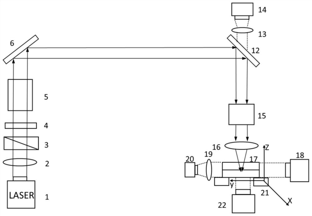
[0045] Such as image 3 As shown, when the distance between the two samples 17 to be welded reaches optical contact, move the integrated second reflector 7 and the fourth total reflector 11 to a designated position and fix it so that it is not on the optical path propagation path, as figure 2 As shown, after the femtosecond laser 1 generates a Gaussian beam G, it passes through the half-wave plate 2, the polarization beam splitter prism 3, the electronically controlled shutter 4 and the laser beam expander 5 in sequence, and is reflected by the first total reflection mirror 6 to the dichroic mirror 12. Then the Gaussian beam G passes through the galvanometer system 15 and the field lens 16 and gathers at the welding interface of the sample to be welded 17 to form a Gaussian beam G welding optical path, and the sample to be welded 17 is fixed on the XYZ mobile welding platform 21 and moved by XYZ Welding platform 21 and galvanometer system 15 adjust and optimize welding proces...

Embodiment 2

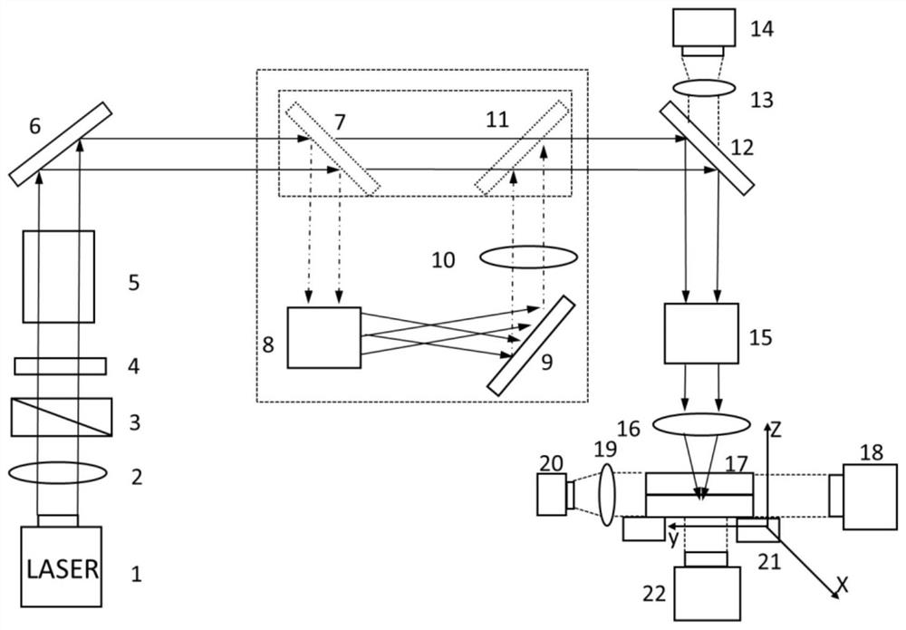
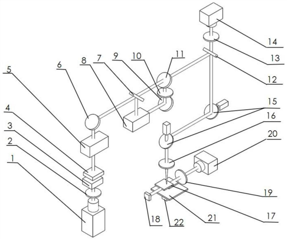
[0047] Such as Figure 4 As shown, when the distance between the two samples 17 to be welded reaches non-optical contact, move the integrated second reflector 7 and the fourth total reflector 11 to a designated position and fix them so that they are on the optical path propagation path, such as image 3 As shown, the Gaussian beam G emitted by the femtosecond laser 1 passes through the half-wave plate 2, the polarizing beam splitter prism 3, the electronically controlled shutter 4 and the laser beam expander 5 in sequence, and is reflected by the first total reflection mirror 6 to the second total reflection mirror 7, Then the Gaussian beam G is shaped into a Bessel beam B by the reflective spatial light modulator 8, and the Bessel beam B passes through the third total reflection mirror 9, the aperture 10, the fourth total reflection mirror 11 and the dichroic mirror 12 , the galvanometer system 15 and the field mirror 16 are gathered at the welding interface of the sample 17 ...


PUM


Abstract

The invention provides a double-light-path ultrafast laser welding device based on light beam shaping. The double-light-path ultrafast laser welding device comprises a femtosecond laser, a half-wave plate, a polarization splitting prism, an electric control shutter, a laser beam expander, a first holophote, a dichroscope, a galvanometer system, a field lens, a to-be-welded sample and an XYZ movable welding platform. Gaussian beams emitted by the femtosecond laser sequentially pass through the half-wave plate, the polarization splitting prism, the electric control shutter, the laser beam expander, the first holophote, the dichroscope, the galvanometer system and the field lens and then are gathered on a to-be-welded sample, and the to-be-welded sample is fixed on the XYZ movable welding platform to form a Gaussian light beam welding light path. A Bessel light beam conversion system is arranged between the first holophote and the dichroscope to form a Bessel light beam laser welding light path. The invention further provides a machining method using the device. According to the welding device, double-light-path welding of different laser beams is achieved, the welding device is suitable for non-optical contact welding and optical contact welding, the welding quality can be effectively improved, and the production cost can be effectively reduced.

Description

technical field [0001] The invention relates to the field of ultrafast laser beam shaping micro-welding processing, in particular to a beam shaping-based dual-optical path ultrafast laser welding device and a processing method. Background technique [0002] Transparent and brittle materials (such as glass, ceramics, sapphire, silicon, etc.) generally have the characteristics of good thermal and chemical stability, as well as high strength, high hardness, low density, wear resistance and corrosion resistance. And it is widely used in the manufacturing or assembly process of micro components, devices or systems including microelectronic packaging, implantable medical devices, micro sensors, converters, batteries, optoelectronic devices, etc. At present, traditional sealing methods for transparent and brittle materials mainly include gluing, solid-phase bonding, anodic bonding, and fusion welding. These traditional bonding / welding processes mentioned above have been difficult ...

Claims


Application Information

Patent Timeline
Patent Type & Authority Applications(China)
IPC IPC(8): B23K26/21B23K26/082B23K26/067B23K26/064B23K26/06B23K26/03B23K26/70
CPCB23K26/21B23K26/064B23K26/0643B23K26/0648B23K26/0652B23K26/082B23K26/067B23K26/702B23K26/032
Inventor 龙雨纪昌豪蒋佶岩陈旭
Owner GUANGXI UNIV
Why Eureka
Try Eureka