
Single-mode micro laser based on single echo wall mode optical microcavity and implementation method

A technology of whispering gallery mode and optical microcavity, applied in the structure of optical resonator, laser, laser parts, etc., can solve the complex preparation process, increase the pumping threshold and laser line width of the microlaser, and reduce the quality factor of the microcavity and other problems to achieve the effect of high quality factor

Active Publication Date: 2021-10-15
EAST CHINA NORMAL UNIV
View PDF9 Cites 5 Cited by
  • Summary
  • Abstract
  • Description
  • Claims
  • Application Information

AI Technical Summary

Problems solved by technology

For single-mode lasing, the size of the whispering gallery mode optical microcavity (hereinafter referred to as the optical microcavity) is usually required to be on the submicron scale to obtain a large free spectral range, which inevitably increases the bending radiation loss of the microcavity and reduces the Improve the quality factor of the microcavity, significantly increase the pumping threshold and laser linewidth of the microlaser
[0003] At present, in order to overcome this difficulty, the commonly used and effective method is to use the vernier effect of two coupled optical microcavities to only excite the whispering gallery mode shared by the two microcavities to obtain a single-mode excitation with low threshold and narrow linewidth. However, the method exists The preparation process is complex and difficult to prepare on a large scale

Method used


Image

  • Single-mode micro laser based on single echo wall mode optical microcavity and implementation method
  • Single-mode micro laser based on single echo wall mode optical microcavity and implementation method
  • Single-mode micro laser based on single echo wall mode optical microcavity and implementation method

Examples


Embodiment 1

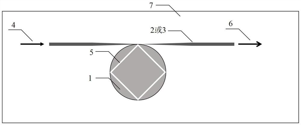
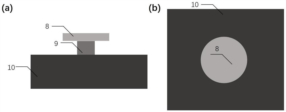
[0034] 1) The optical fiber taper is coupled with the erbium-doped lithium niobate thin film optical microcavity, such as Figure 4 As shown, taking the wafer of lithium niobate thin film 8 doped with 1mol% erbium ions as an example, a layer of chromium film with a thickness of 700nm is plated on it as a mask, and an optical microcavity of the required size is etched by a femtosecond laser. About 30 microns in diameter, it sits on a 2 µm-thick silicon dioxide layer pillar 9, supported by an underlying lithium niobate substrate 10, and has a free spectral range of about 13 nm around a wavelength of 1550 nm, which is about the gain of erbium ions Half of the bandwidth (1535~1560 nm). The microcavity after femtosecond laser etching, combined with chemical mechanical polishing technology (R. Wu, et al., Opt. Lett., Vol. 43, P 4116-4118, 2018) to obtain smooth edges doped with erbium ions Whispering gallery mode optical microcavity 1, the silicon dioxide ball is used as a 60nm pol...

Embodiment 2

[0042] The optical waveguide is coupled with the quantum dot optical microcavity, such as Figure 5 shown

[0043] 1) Use a femtosecond laser to etch an optical microcavity containing quantum dots of the required size. After the femtosecond laser etches the microcavity, the free spectral range of the optical microcavity is at least 1 / 2 of the spectral width of the material containing quantum dots , combined with chemical mechanical polishing technology (R. Wu, et al., Opt. Lett., Vol. 43, P 4116-4118, 2018) to obtain an optical microcavity with smooth edges. Before polishing, carefully clean the gold velvet polishing pad to prevent the small particles inside from scratching the optical microcavity. Ultrasonic methods can be used for deep cleaning. The polished microcavity removes organic matter and particles on the surface by ultrasonic and cotton swab scrubbing, making the surface of the optical microcavity cleaner and reducing loss.

[0044] 2) Use photolithography or dry ...


PUM

PropertyMeasurementUnit
diameteraaaaaaaaaa

Abstract

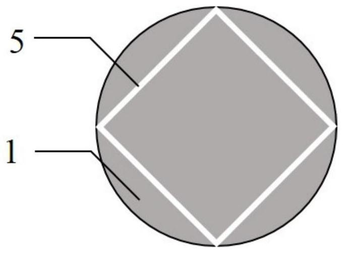
The invention discloses a single-mode micro-laser based on a single echo wall mode optical microcavity and an implementation method, the implementation method comprises the steps of: preparing the required single echo wall mode optical microcavity doped with rare earth ions or containing gain materials such as quantum dots, wherein the configuration of the optical microcavity comprises a microdisk cavity, an annular microcavity and a runway-shaped microcavity, wherein the materials comprise lithium niobate, silicon dioxide, silicon nitride and the like; preparing an optical fiber taper or optical waveguide which has a required size and can excite an optical microcavity high-order mode, wherein the optical fiber taper or optical waveguide comprises a ridge waveguide, a circular waveguide and the like; and coupling, integrating and packaging the optical fiber taper or the optical waveguide and the microcavity. Pump light is coupled to an optical fiber taper or an optical waveguide, a composite mode which is formed by overlapping a fundamental mode and a high-order mode of an optical microcavity and is of a polygonal structure is excited, and the composite mode has a higher quality factor than a fundamental longitudinal mode. The pump light and the laser light are enabled to resonate with the composite mode respectively to obtain low-threshold and narrow-linewidth single-mode laser.

Description

technical field [0001] The invention relates to the preparation of a single-mode micro-laser, specifically a single-mode laser based on a single whispering gallery mode optical microcavity and its preparation, which is doped with a certain concentration of rare earth ions, organic macromolecules or quantum dots through femtosecond laser etching. Crystal, silicon dioxide, silicon, III-V compound semiconductor materials, silicon nitride and other thin film materials, combined with chemical polishing technology, to obtain an optical microcavity with low loss and high Q value, and finally through the optical fiber taper or optical waveguide Coupled and integrated, a single-mode microlaser with narrow linewidth and low threshold is obtained. Background technique [0002] Integrated optical circuit aims to miniaturize and integrate optical devices and optical circuits on the substrate, reduce the size, energy consumption, and delay of the optical system, improve the stability and ...

Claims


Application Information

Patent Timeline
Patent Type & Authority Applications(China)
IPC IPC(8): H01S5/10H01S5/065
CPCH01S5/1042H01S5/0653B82Y20/00H01S5/1075H01S5/3412H01S2301/163H01S5/1032H01S3/0637H01S3/1608H01S3/169H01S3/1628H01S3/1022H01S5/041G02B6/25H01S5/2206H01S5/026H01S5/0654H01S5/02251H01S5/1014H01S5/1028
Inventor 程亚林锦添方致伟高仁宏管江林汪旻
Owner EAST CHINA NORMAL UNIV
Learn More