Preparation method of carbon material loaded tubular carbon nitride photocatalyst

A technology of carbon materials and catalysts, which is applied in the field of preparation of tubular carbon nitride photocatalysts, can solve the problems of high photogenerated electron-hole recombination rate and narrow visible light absorption range, and achieve fast separation and migration rates and red visible light absorption range. The effect of shifting and low production cost

Pending Publication Date: 2021-11-02
NORTHEASTERN UNIV
View PDF5 Cites 2 Cited by
  • Summary
  • Abstract
  • Description
  • Claims
  • Application Information

AI Technical Summary

Problems solved by technology

However, g-C 3 N 4 Like other traditional photocatalysts (metal oxides, metal sulfides), they have the disadvantages of high photogenerated electron-hole recombination rate and narrow visible light absorption range.

Method used


Image

  • Preparation method of carbon material loaded tubular carbon nitride photocatalyst
  • Preparation method of carbon material loaded tubular carbon nitride photocatalyst
  • Preparation method of carbon material loaded tubular carbon nitride photocatalyst

Examples


Embodiment 1

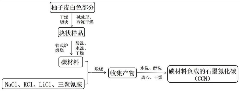
[0060] A method for preparing a carbon material-supported tubular carbon nitride photocatalyst.

[0061] Peel the pomelo until the pulp is separated, and then process it with a knife, leaving only the white part between the pomelo skin and the pomelo pulp. The white part was cut into small pieces, and dried in a hot blast drying oven at 60°C for 24 hours. Subsequently, after soaking the dried sample in 1 M KOH solution for 12 hours, the obtained sample was freeze-dried for 48 hours. Next, the processed samples were ground in turn to make powder into a crucible and placed in a tube furnace. Nitrogen gas is passed into the tube furnace to carbonize the sample at high temperature in the nitrogen environment. Firstly, it was raised to 300°C for 2.5 hours and kept for 1 hour; then it was raised to 600°C for 1 hour and kept for 0.5 hours; finally it was raised to 800°C for 1 hour and kept for 1 hour, and then cooled to room temperature naturally. Grind the obtained black solid in...

Embodiment 2

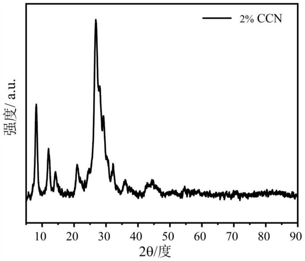
[0065] A preparation method of a carbon material-supported tubular carbon nitride photocatalyst is basically the same as the preparation method of the carbon material-supported tubular carbon nitride photocatalyst in Example 1, the only difference being that the quality of the carbon material in Example 2 is 1.4mg.

[0066] The carbon material supported tubular carbon nitride photocatalyst prepared in Example 2 is coded as 2%CCN.

Embodiment 3

[0068] A preparation method of a carbon material-supported tubular carbon nitride photocatalyst is basically the same as the preparation method of the carbon material-supported tubular carbon nitride photocatalyst in Example 1, the only difference being that the quality of the carbon material in Example 2 is 3.5mg.

[0069] The carbon material supported tubular carbon nitride photocatalyst prepared in Example 3 is numbered 5%CCN.


PUM


Abstract

The invention belongs to the field of nano materials, and discloses a preparation method of a carbon material loaded tubular carbon nitride photocatalyst. The photocatalyst with large specific surface area, multiple active sites, high photon-generated carrier separation and migration rate, low photon-generated carrier coincidence rate, visible light absorption red shift, high photocatalytic activity and high stability is obtained by adjusting the mass fraction of the carbon material. The preparation method comprises the following steps: S1, uniformly mixing the carbon material with sodium chloride, potassium chloride, lithium chloride and melamine, and calcining in a corundum crucible; in the step S1, the preparation method of the carbon material comprises the following steps: (1) cutting the white part of the shaddock peel into blocks, drying, soaking in a KOH solution, and freeze-drying; (2) calcining a sample in a tubular furnace, and washing the sample with HNO3 and ultrapure water until the sample is neutral to obtain a carbon material; and S2, washing the product with ultrapure water and ethanol, drying and collecting. The photocatalyst obtained by the invention promotes the improvement of the hydrogen production performance by photolysis of water, and provides a new thought for further development of efficient photocatalysts.

Description

technical field [0001] The invention belongs to the field of nanometer materials, and relates to a method for preparing a tubular carbon nitride photocatalyst supported by carbon materials. Background technique [0002] In 1972, two professors, Fujishima A and Honda K of the University of Tokyo, Japan reported the discovery of TiO for the first time. 2 The phenomenon that single-crystal electrodes photocatalytically decompose water to produce hydrogen reveals the possibility of using solar energy to directly decompose water to produce hydrogen, and opens up the research path of using solar energy to photolyze water to produce hydrogen. Although the current photocatalytic water splitting hydrogen production is still in the theoretical research stage, this method has potential practical prospects. [0003] In the past few decades, photocatalysts were mostly based on metal oxides, metal sulfides, and polymeric semiconductors of oxides. While these semiconductors exhibit good ...

Claims


Application Information

Patent Timeline
Patent Type & Authority Applications(China)
IPC IPC(8): B01J27/24C01B32/05C01B3/04
CPCB01J27/24B01J35/004B01J35/0013C01B32/05C01B3/042Y02E60/36
Inventor 杨晓红梁晋楠付海涛安希忠尹若铭赵宏明张浩邹清川
Owner NORTHEASTERN UNIV
Why Eureka
Try Eureka