Carbon nanotube field emission cathode and preparation method thereof
A field emission cathode and carbon nanotube technology, applied in the field of field emission, can solve the problems of poor emission stability of the emission cathode, achieve the effect of increasing emission sites, increasing specific surface area, and improving emission stability
- Summary
- Abstract
- Description
- Claims
- Application Information
AI Technical Summary
Problems solved by technology
Method used
Image
Examples
preparation example Construction
[0040] The embodiment of the present invention also provides a method for preparing the carbon nanotube field emission cathode as described above, the preparation method comprising the following steps:
[0041] S10, providing carbon nanotubes and having carboxylic acid groups on their surfaces through a surface treatment process.
[0042] Specifically, the step S10 includes: mixing the carbon nanotubes with the acid solution and then refluxing the reaction at a temperature of 100°C to 200°C for 1h to 10h, and then washing with deionized water for several times to obtain a carbon nanotube with carboxylic acid groups on the surface. group of carbon nanotubes.
[0043] In a preferred scheme, the carbon nanotubes are subjected to HF and HNO 3 The mixed solution was purified and then added concentrated nitric acid, followed by reflux reaction, and then washed with deionized water for many times to obtain carbon nanotubes with carboxylic acid groups on the surface. Wherein, the te...
Embodiment 1
[0058] This embodiment provides a carbon nanotube field emission cathode and a preparation method thereof, including:
[0059] 1) Change CH 4 The carbon nanotubes are prepared by catalytic cracking at 700°C.
[0060] 2) subjecting the carbon nanotubes to HF and HNO 3 After the mixed solution was purified, concentrated nitric acid was added, and then refluxed at 140° C. for 2 hours, and then washed with deionized water several times to obtain carbon nanotubes with carboxylic acid groups on the surface.
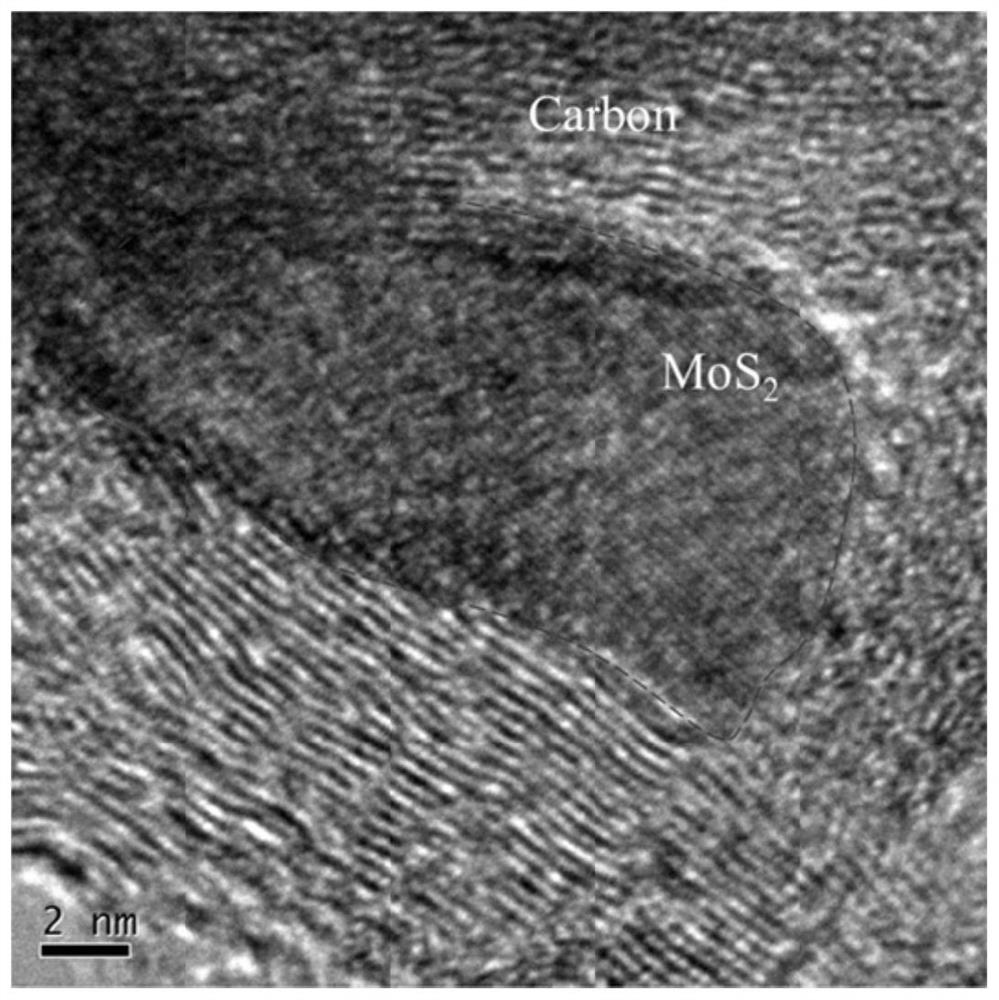
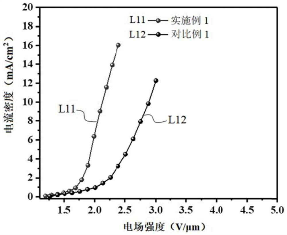
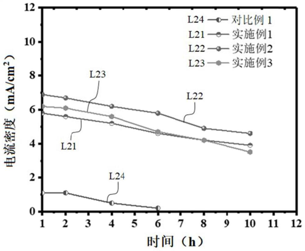
[0061] 3) 0.3g molybdenum sulfate, 0.5g thiourea, 0.5mL hydrogen peroxide (concentration is 30%) and 0.05g step 2) the carbon nanotube that obtains is put into autoclave polytetrafluoroethylene liner, and add A certain amount of deionized water was ultrasonically dispersed for 30 minutes, put into a stainless steel sleeve and sealed, kept at a constant temperature of 240°C for 24 hours, after cooling down to room temperature naturally, it was filtered and rinsed with ethanol ...
Embodiment 2
[0067] The difference between this example and example 1 is that step 3) is a different process for preparing carbon nanotubes with molybdenum sulfide nanoparticles bound to the surface, and the rest of the process steps are the same as those of example 1.
[0068] Specifically, in step 3), 0.37g ammonium thioacetate, 3.7g molybdenum acetate, 0.1g sodium dodecylsulfonate and 0.05g carbon nanotubes are put into the polytetrafluoroethylene liner of the autoclave, and Add a certain amount of deionized water, ultrasonically disperse for 30 minutes, put it into a stainless steel sleeve and seal it, keep the temperature at 240 ° C for 24 hours, wait for natural cooling to room temperature, filter and rinse with ethanol and deionized water, and then vacuum dry the sample at 80 ° C , to obtain carbon nanotubes with molybdenum sulfide nanoparticles bound on the surface.
PUM
| Property | Measurement | Unit |
|---|---|---|
| diameter | aaaaa | aaaaa |
| length | aaaaa | aaaaa |
| particle diameter | aaaaa | aaaaa |
Abstract
Description
Claims
Application Information
 - R&D
- Intellectual Property
- Life Sciences
- Materials
- Tech Scout
- Unparalleled Data Quality
- Higher Quality Content
- 60% Fewer Hallucinations
Browse by: Latest US Patents, China's latest patents, Technical Efficacy Thesaurus, Application Domain, Technology Topic, Popular Technical Reports.
© 2025 PatSnap. All rights reserved.Legal|Privacy policy|Modern Slavery Act Transparency Statement|Sitemap|About US| Contact US: help@patsnap.com


