Dry-type granulated slag and sludge coupling drying process and device

A dry granulation and sludge drying technology, which is applied in dehydration/drying/thickened sludge treatment, process efficiency improvement, drying, etc., can solve the problems of unfavorable continuous utilization, low added value, high energy consumption cost, etc. , to achieve the effect of solving the problem of effective utilization, rapid heat absorption and release, and high utilization rate of heat energy

Active Publication Date: 2022-02-18
BAOSHAN IRON & STEEL CO LTD
View PDF8 Cites 1 Cited by
  • Summary
  • Abstract
  • Description
  • Claims
  • Application Information

AI Technical Summary

Problems solved by technology

[0006]2. A lot of water resources are wasted: the water pressure is greater than 0.2MPa during the process of washing slag with water, the ratio of slag to water is 1:10, and 0.8 fresh water is consumed per ton of slag ~1.2 tons
[0007]3. Produce harmful gases such as SO2 and H2S, polluting the environment: during the process of washing slag with water Produce a large amount of H2S and SOx, which are discharged into the atmosphere with water vapor, and become the cause of acid rain when they accumulate to a certain extent
[0010]1. The granulation effect is not good, which is not conducive to continued utilization: the cold slag obtained by the internal cooling drum method is discharged in the form of flakes, which is not conducive to the its continued use
The particle diameter distribution range of the granulated slag obtained by the air quenching method is wide, which is not conducive to subsequent processing
The flat-plate slag obtained by the continuous casting and rolling method is in the form of large flakes, which is not conducive to its continued utilization
[0011]2. The quality of the heat exchange gas is not high: the centrifugal disc method uses a fluidized bed for heat exchange, the bed layer is back-mixed violently, and the outlet temperature is not high at 400-500 ℃, the energy quality is low, and the high temperature heat source has not been effectively utilized
[0012]3. Low heat recovery efficiency: the heat absorbed by the internal heat medium in the internal cooling drum method is about 40% of the sensible heat of the slag, and the continuous casting and rolling method The air permeability of the obtained flat high-temperature slag seriously affects the heat transfer efficiency of the cold air and the water wall
[0013]4. The degree of vitrification is not high, and the added value is low: the rotary granulation method belongs to semi-quick cooling treatment, and the obtained product is concrete aggregate, with low added value
The slag particles obtained by mechanical stirring method are large and uneven in size, and the degree of vitrification is not high, so they can only be used as paving materials
[0014]5. High equipment operation cost and large investment: the air quenching method consumes a lot of power during the granulation process, and the air quenching cooling speed is relatively slow. In order to prevent the granulated slag Adhesion to equipment surfaces prior to consolidation requires larger equipment dimensions, increasing investment costs
[0018] Sludge drying technology is the premise and basis for realizing sludge disposal and resource utilization. Traditional sludge drying technology has high energy consumption and high cost of sludge moisture content from 80 % to 20%, the energy consumption per ton of sludge drying exceeds 740 kilowatt-hours, equivalent to about 90kg of standard coal, which seriously restricts the development and application of sludge drying technology

Method used


Image

  • Dry-type granulated slag and sludge coupling drying process and device
  • Dry-type granulated slag and sludge coupling drying process and device
  • Dry-type granulated slag and sludge coupling drying process and device

Examples


Embodiment Construction

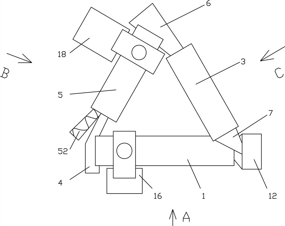
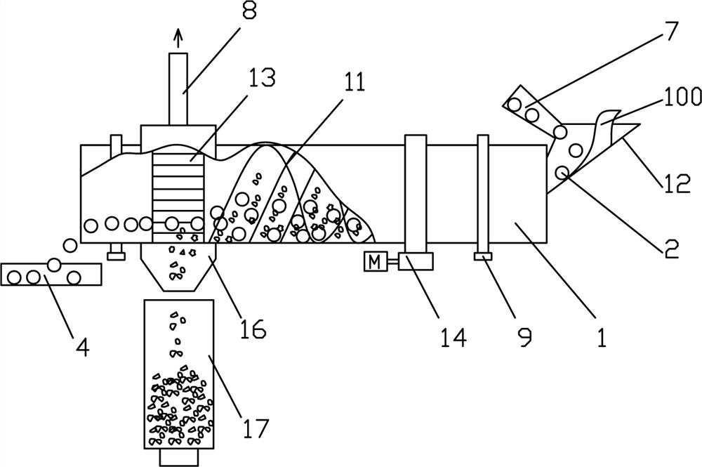
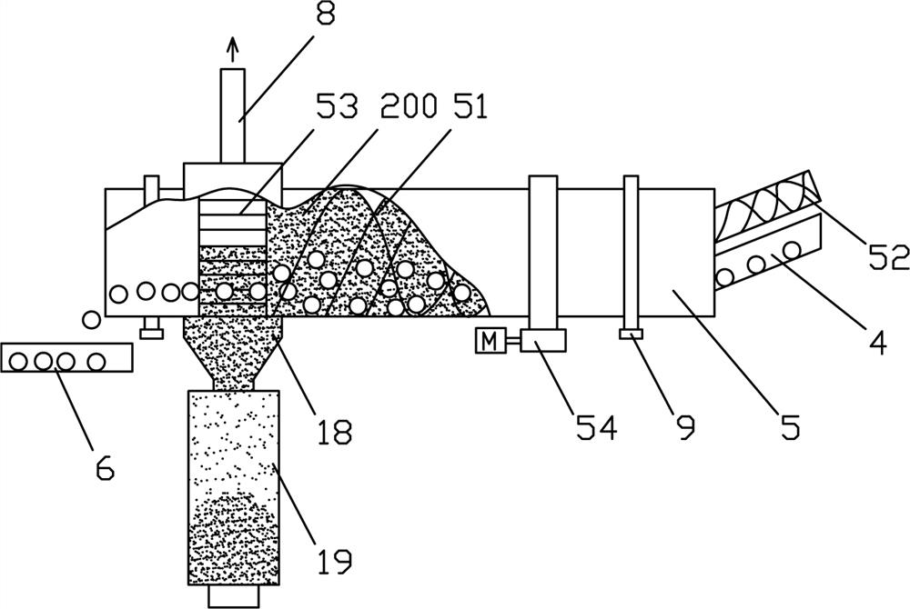
[0064] see Figure 1 ~ Figure 4 , the dry granulated slag and sludge coupling drying device according to the present invention, which includes,

[0065] Slag cooling treatment device 1, which is a cylinder structure, the inner wall is provided with a propulsion mechanism 11, a slag feeding funnel 12 is provided at the slag inlet, and a slag discharge mechanism 13 is provided at the outlet; the slag cooling treatment 1 device is connected to a A first driving device 14 that can drive it to rotate;

[0066] A plurality of steel balls 2 and a steel ball conveying device 3, the steel ball conveying device 3 is connected to the inlet of the slag cooling treatment device 1;

[0067] A high-temperature steel ball chute 4, one end of which is connected to the outlet of the slag cooling treatment device 1;

[0068] The sludge drying device 5 is a cylinder structure, the inner wall is provided with a propulsion mechanism 51, a sludge conveying device 52 is provided at the sludge inlet...


PUM


Abstract

The invention discloses a dry-type granulated slag and sludge coupling drying process and device, and the process comprises the following steps: 1) mixing and soaking slags and balls, and fully mixing and exchanging heat of high-temperature slags and steel balls, so that the heat of the high-temperature slags is rapidly absorbed by the steel balls and the high-temperature slags are cooled and crushed to form granular slags, and the temperature of the steel balls rises by absorbing the heat of the high-temperature slags; and 2) sludge drying: conveying the high-temperature steel balls to a sludge drying device, mixing the high-temperature steel balls with the injected sludge, drying the sludge, separating the steel balls from the sludge when the water content of the sludge reaches a set value, and respectively discharging the steel balls and the sludge. According to the invention, the temperature of the steel balls is increased by using the waste heat of the high-temperature molten slags, and the sludge is dried by the heated steel balls, so that the cooperative treatment of molten slag cooling, granulating and sludge drying is realized, the two problems of molten slag cooling and sludge drying are solved, and the recycling rate of the waste heat of the high-temperature molten slag is greatly increased.

Description

technical field [0001] The invention relates to the technical field of waste heat recovery of metallurgical slag, in particular to a process and device for coupled drying of dry granulated slag and sludge. Background technique [0002] China is currently the world's largest steel producer. China's steel output has remained the world's largest for 16 consecutive years, and it is far ahead of other countries. In 2019, the steel output in mainland China was 996 million tons. The heat contained in the slag generated in the process of smelting steel is huge. From the perspective of energy saving and environmental protection and improving the economic benefits of steel plants, the heat recovery and high-efficiency of blast furnace slag The resource utilization of slag is very necessary. The temperature of blast furnace slag is generally between 1400 and 1550 °C. Each ton of slag contains (1260~1880)×10 3 The sensible heat of kJ is equivalent to the calorific value of 60kg stand...

Claims


Application Information

Patent Timeline
Patent Type & Authority Applications(China)
IPC IPC(8): C21B3/08
CPCC21B3/08C21B2400/022C21B2400/08C21B2400/05C02F11/13Y02P10/20Y02W30/50C21B2400/064C21B2400/056C21B2400/066C21B2400/026F26B11/0481F26B11/0472F26B3/205F26B11/026
Inventor 肖永力李永谦
Owner BAOSHAN IRON & STEEL CO LTD
Why Eureka
Try Eureka