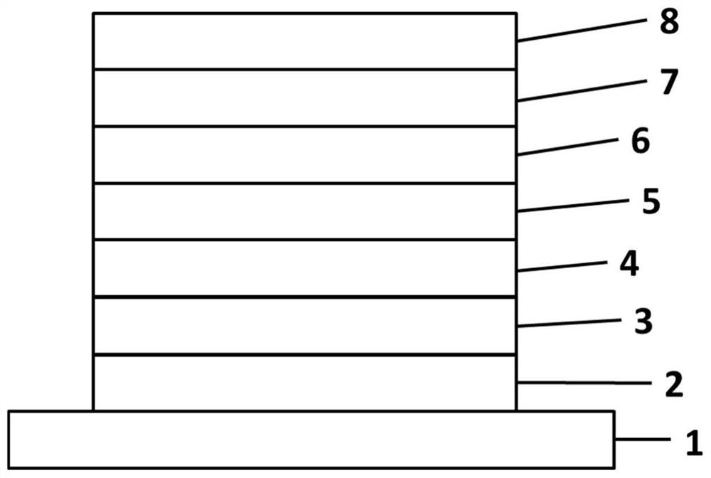
Organic light emitting device
A technology of organic light-emitting devices and organic layers, which is applied in the manufacture of semiconductor devices, electric solid-state devices, and semiconductor/solid-state devices, etc., can solve the problems of inability to display good effects, difficulty in using blue fluorescent light-emitting devices, and large differences in light-emitting systems.
- Summary
- Abstract
- Description
- Claims
- Application Information
AI Technical Summary
Problems solved by technology
Method used
Image

Examples
Embodiment
[0162] In order to facilitate understanding of the present invention, the present invention enumerates the following examples. It should be clear to those skilled in the art that the embodiments are only for helping to understand the present invention, and should not be regarded as specific limitations on the present invention.
[0163] Synthetic example
Synthetic example 1
[0165] The preparation method of compound A102
[0166]
[0167] Synthesis of Intermediate A102-M1
[0168] The compound 2-bromo-4-phenylaniline (50.0g, 202mmol) synthesized in the previous step, dibenzofuran-4-boronic acid (47.1g, 222mol), and potassium carbonate (36.2g, 262mmol) were placed in a 1000mL three-port In the bottle, stir well, then replace the air on the bottle with nitrogen three times, add tetrakistriphenylphosphine palladium (4.66g, 4.03mmol) into the reaction solution under the protection of nitrogen, then raise the temperature to 100°C, and react for 18h. After cooling down, the reaction solution was poured into a saturated aqueous ammonium chloride solution, extracted with ethyl acetate (500 mL, three times), the organic phases were combined, dried over anhydrous sodium sulfate, filtered, and concentrated to obtain a brown-red oil. The crude product was purified by silica gel chromatography (petroleum ether / ethyl acetate, 10 / 1) to obtain a yellow solid....
Synthetic example 2
[0176] The preparation method of compound A148
[0177]
[0178] Take compound A102-M2 (15g, 30.8mmol), 2-(4-bromophenyl)-9,9 dimethylfluorene (11.8g, 33.8mmol) and sodium tert-butoxide (3.55g, 36.9mmol) into Put it into a 500mL three-necked flask filled with 200mL of toluene, stir well to dissolve. The air in the bottle was then fully replaced with nitrogen, followed by the catalyst tris(dibenzylideneacetone)dipalladium (282 mg, 0.308 mmol) and 2-bicyclohexylphosphine-2',6'-dimethoxybiphenyl (505 mg , 1.23mmol) was added to the reaction solution, and the temperature was raised to reflux for 18h. After cooling down, the reaction solution was poured into saturated ammonium chloride aqueous solution, extracted with ethyl acetate (200 mL, three times), the organic phases were combined, dried over anhydrous sodium sulfate, filtered, and concentrated to obtain a brown-black oil. The crude product was purified by a silica gel layer column (petroleum ether / dichloromethane, 15 / 1)...
PUM
| Property | Measurement | Unit |
|---|---|---|
| Thickness | aaaaa | aaaaa |
Abstract
Description
Claims
Application Information
 - R&D
- Intellectual Property
- Life Sciences
- Materials
- Tech Scout
- Unparalleled Data Quality
- Higher Quality Content
- 60% Fewer Hallucinations
Browse by: Latest US Patents, China's latest patents, Technical Efficacy Thesaurus, Application Domain, Technology Topic, Popular Technical Reports.
© 2025 PatSnap. All rights reserved.Legal|Privacy policy|Modern Slavery Act Transparency Statement|Sitemap|About US| Contact US: help@patsnap.com