

Electroluminescent phosphorescence material and its application
A phosphorescent material and luminescent technology, applied in the field of phosphorescent materials, can solve problems such as poor compatibility
- Summary
- Abstract
- Description
- Claims
- Application Information
AI Technical Summary
Problems solved by technology
Method used
Image

Examples
Embodiment 1
[0057] Example 1 Compound 1 (TFPBO) 2 IrBPBPIr(TFPBO) 2 Synthesis
[0058] 1) (TFPBO) 2 Ir(μ-Cl) 2 Ir(TFPBO) 2 Synthesis
[0059] Weigh 0.3553 g of IrCl 3 ·nH 2 O (1mmol), 0.5345 grams of 2-(2', 3', 4', 5'-tetrafluoro)-phenyl-benzoxazole (TFPBO, 2mmol), were added to 30 milliliters of ethylene glycol monoethyl ether and 10 Milliliters of water mixed solution, heated to reflux for 24 hours under the protection of nitrogen, then cooled to room temperature, there was precipitation. The precipitate was filtered off, dichloromethane was used as eluent, silica gel column chromatography was used, and the solvent was evaporated to obtain 0.892 g of yellow solid powder with a yield of 90%. The structure was confirmed by nuclear magnetic resonance, mass spectrometry and elemental analysis. 1 H-NMR (200MHz, d-acetone,): δ, ppm, 6.84(t, 4H, J7.1Hz), 7.01(t, 4H, J7.0Hz), 7.14(d, 4H, J8.0Hz), 8.18 (d, 4H, J8.3Hz); time-of-flight mass spectrometry (TOF): m / e, 1519; elemental analysi...
Embodiment 2
[0062] Example 2 Compound 2 (TFPBO) 2 IrBPBPIr(TFPBO) 2 Synthesis
[0063] 1) (TFPBO) 2 Ir(μ-Cl) 2 Ir(TFPBO) 2 Synthesis
[0064] Weigh 0.3553 g of IrCl 3 nH 2 O (1mmol), 0.5345 g 2-(2',3',4',5'-tetrafluoro)-phenyl-benzimidazole (TFPBI, 2mmol), was added to 30 ml ethylene glycol monoethyl ether and 10 ml In the mixed solution of water, it was heated to reflux for 24 hours under the protection of nitrogen, and then cooled to room temperature, and a precipitate was deposited. The precipitate was filtered off, dichloromethane was used as eluent, silica gel column chromatography was used, and the solvent was evaporated to obtain 0.892 g of yellow solid powder with a yield of 90%. The structure was confirmed by nuclear magnetic resonance, mass spectrometry and elemental analysis. 1 H-NMR (200MHz, d-acetone,): δ, ppm, 6.84(t, 4H, J7.1Hz), 7.01(t, 4H, J7.0Hz), 7.14(d, 4H, J8.0Hz), 8.18 (d, 4H, J8.3Hz); time-of-flight mass spectrometry (TOF): m / e, 1519; elemental analysis: ex...
Embodiment 3
[0067] Example 3 Compound 3 (TFPBI) 2 IrBPBPIr (TFPBI) 2 Synthesis
[0068] 1) (TFPBI) 2 Ir(μ-Cl) 2 Ir(TFPBI) 2 Synthesis
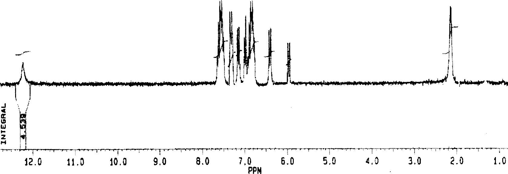
[0069] Weigh 0.3553 g of IrCl 3 nH 2 O (1mmol), 0.5345 grams of 2-(2', 3', 4', 5'-tetrafluoro)-phenyl-benzoxazole (TFPBO, 2mmol), were added to 30 milliliters of ethylene glycol monoethyl ether and 10 Milliliters of water mixed solution, heated to reflux for 24 hours under the protection of nitrogen, then cooled to room temperature, there was precipitation. The precipitate was filtered off, dichloromethane was used as eluent, silica gel column chromatography was used, and the solvent was evaporated to obtain 0.892 g of yellow solid powder with a yield of 90%. The structure was confirmed by nuclear magnetic resonance, mass spectrometry and elemental analysis. 1 H-NMR (200MHz, d-acetone,): δ, ppm, 6.81(t, 4H, J7.1Hz), 7.01(t, 4H, J7.0Hz), 7.14(d, 4H, J8.0Hz), 8.18 (d, 4H, J8.3Hz), 12.17 (s, 4H, heavy water exchange disappeared); time-of-flight mass...
PUM
| Property | Measurement | Unit |
|---|---|---|
| thickness | aaaaa | aaaaa |
| thickness | aaaaa | aaaaa |
| thickness | aaaaa | aaaaa |
Abstract
Description
Claims
Application Information