Method for manufacturing rare earth extended fibre-optical prefabricated bar

An optical fiber preform, rare earth-doped technology, applied in manufacturing tools, glass manufacturing equipment, optics, etc., can solve the problem of low gain flatness, very limited control of doping uniformity and doping concentration, and uniformity restrictions. and other problems, to achieve the effect of improving the utilization rate of raw materials, improving the indicators of optical devices, and improving the uniformity of doping

Inactive Publication Date: 2004-04-21
FENGHUO COMM SCI & TECH CO LTD
View PDF0 Cites 35 Cited by
  • Summary
  • Abstract
  • Description
  • Claims
  • Application Information

AI Technical Summary

Problems solved by technology

[0009] The main problems in the above rare earth-doped optical fiber manufacturing process are the poor doping uniformity of various rare earth ions and co-doped ions, the low doping concentration, and the poor doping amount and composition of various dopants. In the application of optical devices, the gain flatness is not high, and the development of performance such as bandwidth is limited.
In the solution method, other solvents such as water and ethanol are introduced to pollute the core layer of the preform, and the uniformity of doping and the concentration of doping are very limited.
In the gas phase method, the uniformity is also greatly limited due to the uncontrolled evaporation of rare earth compounds and co-dopants.

Method used


Image

  • Method for manufacturing rare earth extended fibre-optical prefabricated bar
  • Method for manufacturing rare earth extended fibre-optical prefabricated bar
  • Method for manufacturing rare earth extended fibre-optical prefabricated bar

Examples


Embodiment 1

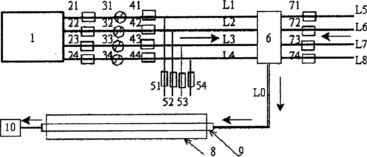
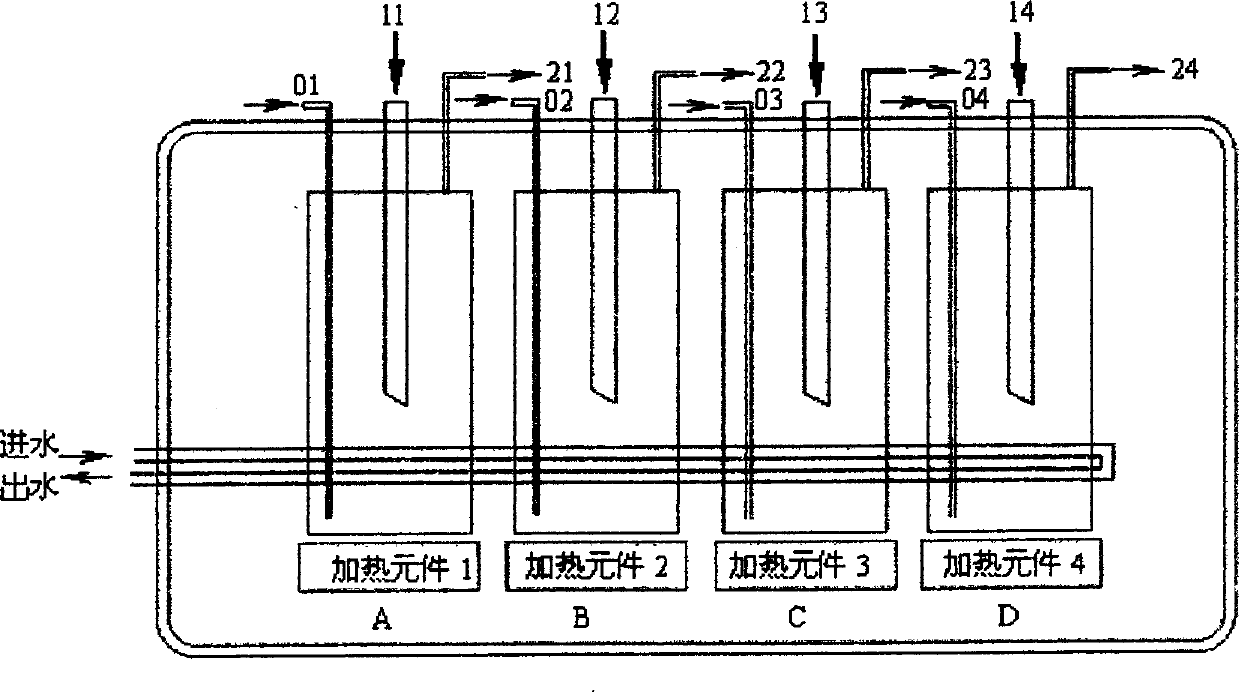
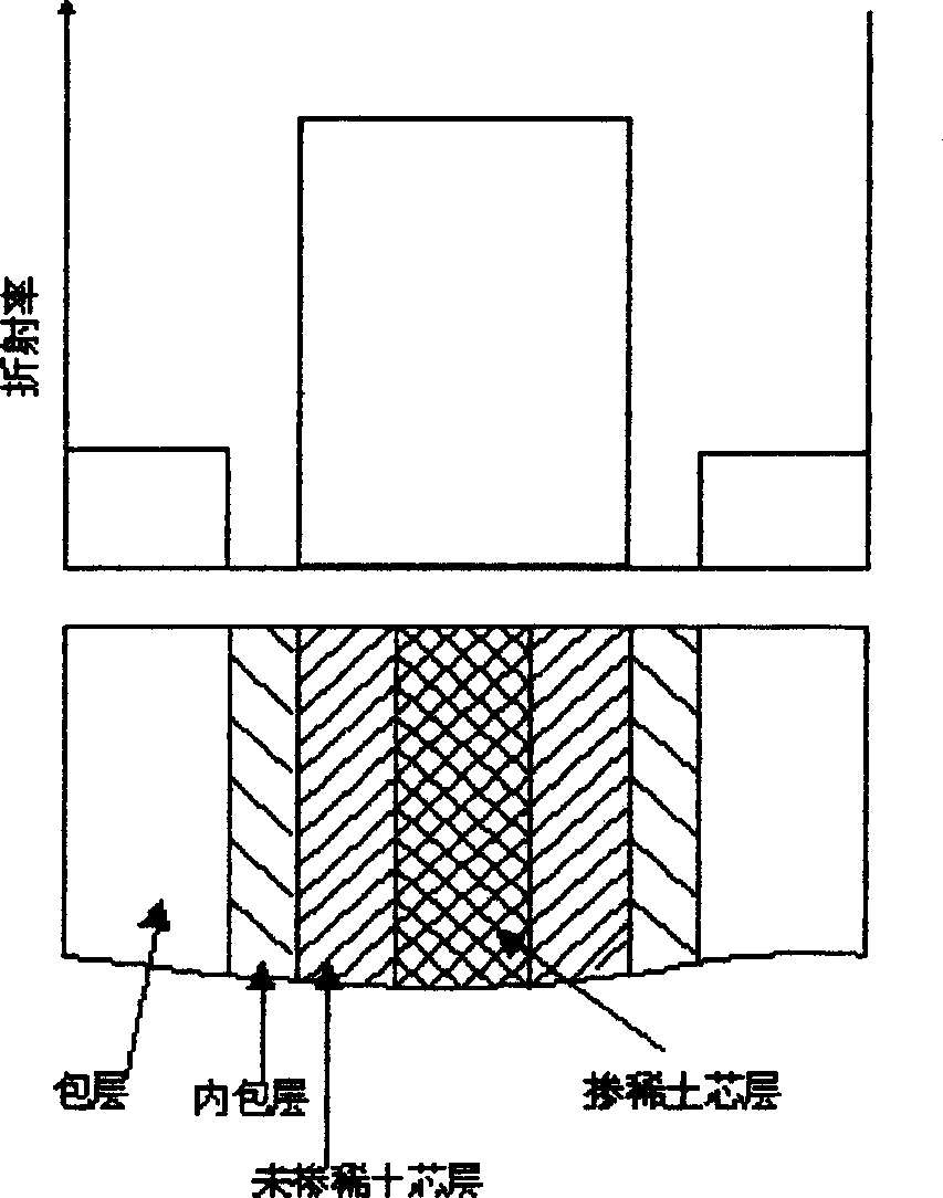
[0029] In the quartz glass tube, silicon tetrachloride, oxygen and dopant sulfur hexafluoride (SF 6 ) for deposition to form an inner cladding layer, and then pass through silicon tetrachloride, germanium tetrachloride, oxygen and dopant sulfur hexafluoride (SF 6 ), phosphorus oxychloride (POCl 3 ) deposition to form the core layer (1), and then silicon tetrachloride, germanium tetrachloride, rare earth compound Yb 2 o 3 and the co-dopant AlCl 3 Use an evaporator to evaporate and mix with oxygen evenly, and finally pass it into a quartz glass tube to deposit a rare earth-doped core layer (2), and use a flow meter to control the flow of various gases, the rare earth compound Yb 2 o 3 The evaporation temperature is 200 °C, the co-dopant AlCl 3 The evaporation temperature is 200°C; after the deposition is completed, the deposition tube is melted and shrunk into a solid preform rod on the shrink rod equipment.

Embodiment 2

[0031] In the quartz glass tube, silicon tetrachloride, oxygen and dopant sulfur hexafluoride (SF 6 ), phosphorus oxychloride (POCl 3 ) for deposition to form an inner cladding, and then pass through silicon tetrachloride, germanium tetrachloride, oxygen and sulfur hexafluoride (SF 6 ), phosphorus oxychloride (POCl 3 ) is deposited to form a core layer (1), and then silicon tetrachloride, germanium tetrachloride, ErCl 3 Rare earth compounds and POCl 3 The co-dopant is evaporated by an evaporator and mixed evenly with oxygen, and the flow of various gases is controlled by a flow meter. The rare earth compound ErCl 3 The evaporation temperature is 300 °C, the co-dopant POCl 3 The evaporation temperature is 300°C; finally, it is deposited in a quartz glass tube, and the deposition temperature is lowered to 1500°C to form a rare earth-doped core layer, and ErCl 3 The above-mentioned core layer is soaked and dried by the rare earth compound solution to form the core layer (2)....

Embodiment 3

[0033] Silicon tetrachloride, oxygen and dopant carbon hexafluoride (C 2 f 6 ) is deposited to form an inner cladding layer, and then silicon tetrachloride, germanium tetrachloride, oxygen and dopant carbon hexafluoride (C 2 f 6 ), phosphorus oxychloride (POCl 3 ) is deposited to form the core layer (1), and then silicon tetrachloride, germanium tetrachloride, rare earth compound TmBr 3 and the co-dopant POCl 3 , AlCl 3 Use an evaporator to evaporate and mix with oxygen evenly, and finally pass it into a quartz glass tube to deposit a rare earth-doped core layer (2), and use a flow meter to control the flow of various gases. The rare earth compound TmBr 3 The evaporation temperature is 200 °C, the co-dopant POCl 3 , AlCl 3 The evaporation temperature is 200°C; after the deposition is completed, the deposition tube is melted and shrunk into a solid preform rod on the shrink rod equipment.

[0034] The rare earth compound in the above embodiment can be: a halide or an ox...


PUM


Abstract

A process for preparing the prefabricated RE-doped optical-fibre rod features that the chemical gas-phase deposition of plasma is used to deposit the doped SiO2 layer on the inner surface of liner quartz tube and the evaporator is used to directly deliver the RE compound and other codoping agent into reaction tube for direct deposition without pollution.

Description

technical field [0001] The invention relates to a method for manufacturing an optical fiber preform, in particular to a method for directly depositing rare earth dopants by using a plasma chemical vapor deposition (PCVD) process to manufacture rare earth doped optical fibers. technical background [0002] In the early 1960s, at the same time as the semiconductor light amplification phenomenon was studied, the spectral characteristics of optical fibers doped with rare earth elements were also studied. At that time, these studies were carried out in anticipation of the development of rare earth fiber laser sources. From 1985 to 1986, Payne and others at the University of Southampton in the United Kingdom effectively solved the problem of thermal quenching of erbium-doped optical fibers, developed a core-doped erbium-doped optical fiber by MCVD for the first time, and achieved a low loss window of 1.55 μm In 1987, they used a 650 dye laser as a pumping ligh...

Claims


Application Information

Patent Timeline
Patent Type & Authority Applications(China)
IPC IPC(8): C03B20/00C03B37/012C03B37/014C03B37/018C03C13/04G02B6/00
CPCC03B2201/31C03B2201/36C03B2207/20C03B2201/34C03B2201/28C03B37/01823
Inventor 尹红兵李诗愈李进延李海清蒋作文陈伟刘学军
Owner FENGHUO COMM SCI & TECH CO LTD
Why Eureka
Try Eureka