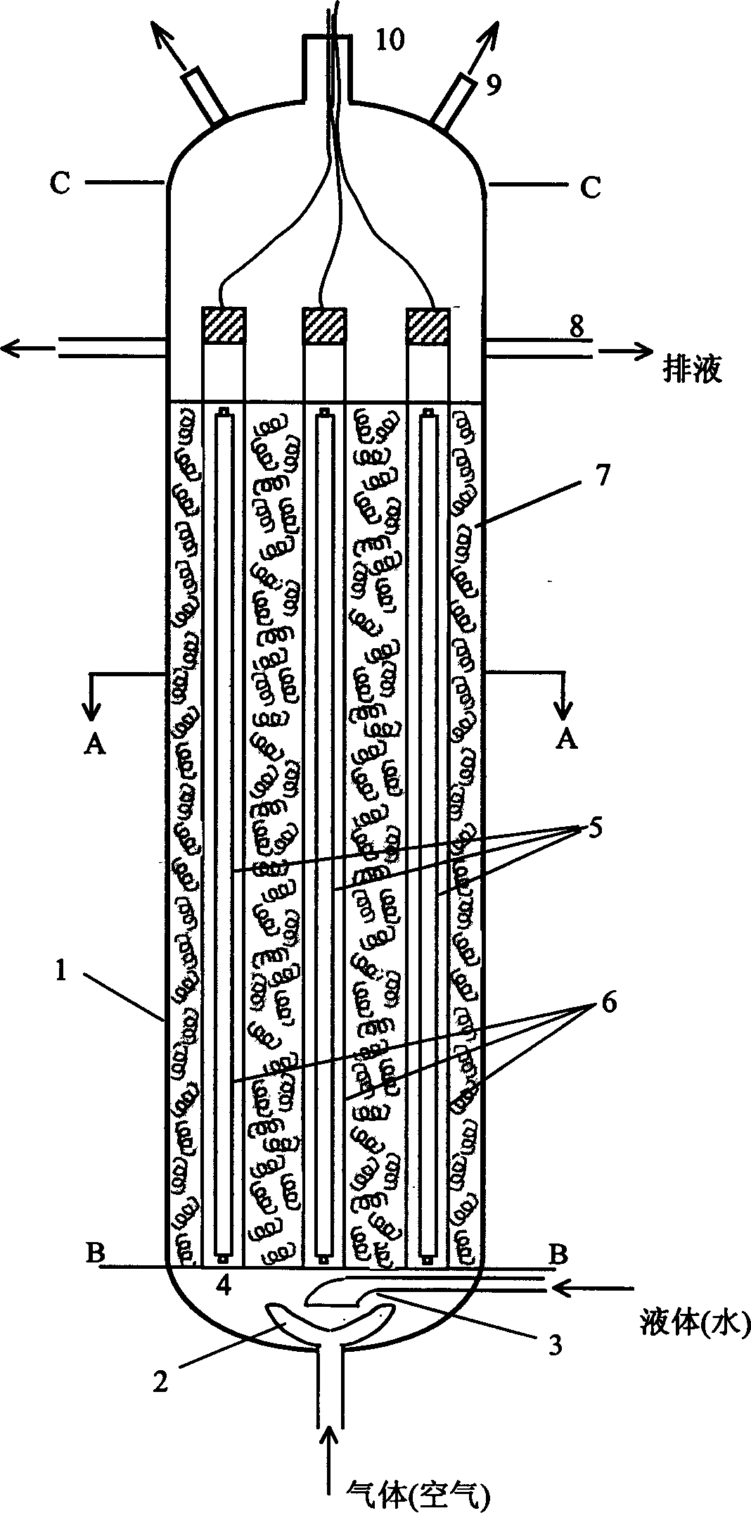
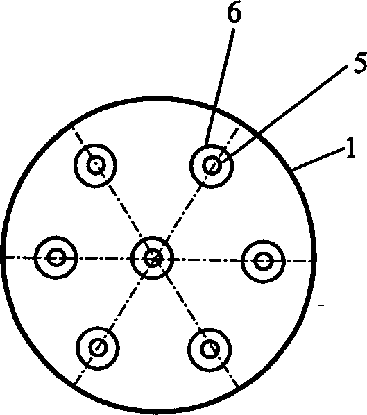
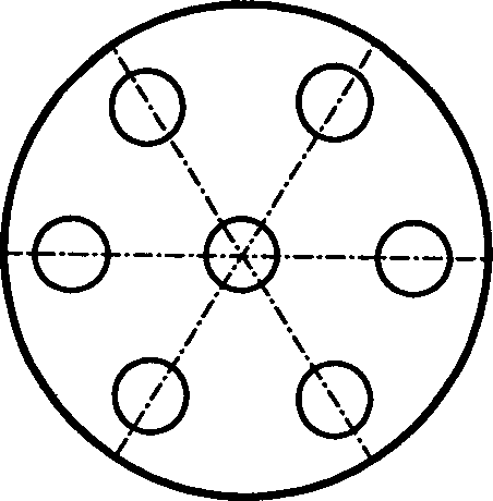
Visible photoactivating photo catalyst and light-column type packed bed reaction unit

A photocatalyst and visible light technology, applied in the direction of physical/chemical process catalysts, catalyst activation/preparation, chemical instruments and methods, etc., can solve the problems of difficult to scale-up applications, narrow ring gap width, poor mass transfer between fluid and catalyst surface and other problems, to achieve the effect of lower temperature, low heat treatment temperature, and excellent photocatalytic activity

Inactive Publication Date: 2004-09-15
EAST CHINA UNIV OF SCI & TECH
View PDF8 Cites 26 Cited by
  • Summary
  • Abstract
  • Description
  • Claims
  • Application Information

AI Technical Summary

Problems solved by technology

[0005] Japanese patent JP 2002166176A2 loads the photocatalyst on a carrier such as glass beads with a particle size of 0.3-5 mm, and then constructs a concentric annular packed bed reactor with an ultraviolet lamp placed in the center of the inner tube. The allowable annular gap width of this reactor is Very narrow, it is difficult to give a solution for enlarged applications
Japanese patent JP 2001239257A2 coats the photocatalyst on th

Method used


Image

  • Visible photoactivating photo catalyst and light-column type packed bed reaction unit
  • Visible photoactivating photo catalyst and light-column type packed bed reaction unit
  • Visible photoactivating photo catalyst and light-column type packed bed reaction unit

Examples


Embodiment 1

[0024] Grind the ammonium bicarbonate thoroughly and add TiCl 4 As a measurement basis, take 1 part (mole) of TiCl 4 , add 4 parts of ammonium bicarbonate and 6 parts of isopropanol in an ice bath, stir and disperse, raise the temperature to 85 °C at a rate of 2 °C per minute, keep the temperature for 2 hours, and then dry it at 150 °C. After the dry powder is ground and pulverized, Soak and wash with deionized water for 3 times, filter and dry, heat treat at 300°C for 2 hours under nitrogen atmosphere, grind and pulverize after cooling to obtain powdery nitrogen-doped titanium dioxide-based photocatalyst.

Embodiment 2

[0026] Grind the ammonium bicarbonate thoroughly and add TiCl 4 As a measurement basis, take 1 part (mole) of TiCl 4 , add 3 parts of ammonium bicarbonate and 4 parts of isopropanol in an ice bath, stir and disperse, raise the temperature to 50 ° C at a rate of 1 ° C per minute, keep the temperature for 1.5 hours, then dry at 120 ° C, dry powder grinding and crushing, Soak and wash with deionized water twice, filter and dry, heat treat at 550° C. for 1 hour under nitrogen atmosphere, grind and pulverize after cooling to obtain powdery nitrogen-doped titanium dioxide-based photocatalyst.

Embodiment 3

[0028] Grind the ammonium bicarbonate thoroughly and add TiCl 4 As a measurement basis, take 1 part (mole) of TiCl 4 , add 6.5 parts of ammonium bicarbonate and 9 parts of isopropanol in an ice bath, stir and disperse, raise the temperature to 92 °C at a rate of 3 °C per minute, keep the temperature for 2 hours, then dry at 150 °C, and place in a nitrogen atmosphere Heat treatment at 250° C. for 3 hours, grind and pulverize after cooling to obtain a powdery nitrogen-doped titanium dioxide-based photocatalyst.


PUM


Abstract

The invention relates to a nitrogen-doped visible photosensitized TiO2 photocatalyst making method as well as its light-array type filling-fixed-bed photocatalysis fluid processing method and device. It evenly produces water and ammonia at the same time in the system by ammonium bicarbonate thermolysis, to make titanium tetrachloride carry out even hydrolysis and ammonolysis reactions to produce nitrogen-doped metatitanic acid fore body, which is treated at the nitrogen atmosphere under low temperature to obtain visible photosensitized nitrogen-doped nano TiO2 film or powder. The glass-tube ultraviolet light cannulas are uniformly distributed in the light-array type reactor, where the load-type photocatalyst is filled in the huddling mode in the air gap between the cannulas. It has advantages of moderate reacting condition, low heat treating temperature, etc. The photocatalysis reactor has advantages of continuous running, convenient operation, high efficiency, etc; can be applied to sewage treatment, drinking water's deep purification, waste gas treatment, etc.

Description

technical field [0001] The invention relates to a visible light sensitized photocatalyst preparation method for photocatalytic water treatment and air purification and a column lamp type filled fixed bed photocatalytic reaction device. Background technique [0002] Photocatalytic water treatment and air purification technology is a very promising environmental pollution control technology, and has some practical applications. At present, the photocatalyst that has been extensively studied and considered to have the most application value is TiO 2 . Under the excitation of light, TiO 2 The valence band electrons of the photocatalyst are excited to its conduction band, photogenerated holes and electrons are generated in the valence band and conduction band respectively, and these photogenerated carriers migrate to TiO 2 The surface of the particles is captured by surface species (such as -OH, adsorbed water and oxygen, etc.), generating reactive oxy...

Claims


Application Information

Patent Timeline
IPC IPC(8): B01J21/06B01J37/03C02F1/30
CPCY02W10/37
Inventor 陈爱平刘伟卢冠忠邱玮刘威干大川戴智铭
Owner EAST CHINA UNIV OF SCI & TECH
Why Eureka
Try Eureka