Micro-lens forming method by means of wet method side guide

A technology of microlens and guide, applied in the direction of lens, microlithography exposure equipment, optics, etc., can solve the problems of affecting the optical quality of components, increasing the cost of components, complicated polishing process, etc., and achieve the improvement and reduction of relief depth and numerical aperture Production cost and the effect of expanding the scope of production

Inactive Publication Date: 2006-06-21
INST OF OPTICS & ELECTRONICS - CHINESE ACAD OF SCI
View PDF0 Cites 2 Cited by
  • Summary
  • Abstract
  • Description
  • Claims
  • Application Information

AI Technical Summary

Problems solved by technology

During this process, due to the pollution of metal ions, carbon polymers and reaction products, various defects will grow on the surface of the component, which will seriously affect the optical quality of the component; in addition, the ICP dry process equipment is expensive, the consumption of etching gas is large, and the etching process is difficult. For a long time, these problems have increased the cost of components
Although the diamond turning technology does not need to pre-fabricate photoresist microlenses, there are two key shortcomings in making microlenses with diamond turning equipment: (1) It is difficult to process brittle materials such as quartz (the existing diamond Knife equipment is mainly used for processing plastics, metals and other materials); (2) After the turning is completed, there are car marks on the surface of the component, which requires a complicated polishing process for subsequent processing
[0003] In short, since the traditional microlens production needs to use ICP plasma equipment for dry etching, the microlenses made of resist material are converted into high-damage resistant quartz and glass microlens arrays required for practical applications. , the microlens array is polluted by metal ions, carbon polymers and etching products, not only has a large number of defects (dirty spots, bumps, etc.) on the surface, but also the yield of components is extremely low
This leads to a rapid increase in the production cost of microlenses, which severely limits the expansion of the application range of components.

Method used


Image

  • Micro-lens forming method by means of wet method side guide
  • Micro-lens forming method by means of wet method side guide
  • Micro-lens forming method by means of wet method side guide

Examples


Embodiment 1

[0029] Embodiment 1, make aperture φ=500 μm, interval 200 μm (total 5), the quartz material continuous embossment microcylindrical lens array of etching depth h=3 μm, its manufacturing process is as follows:

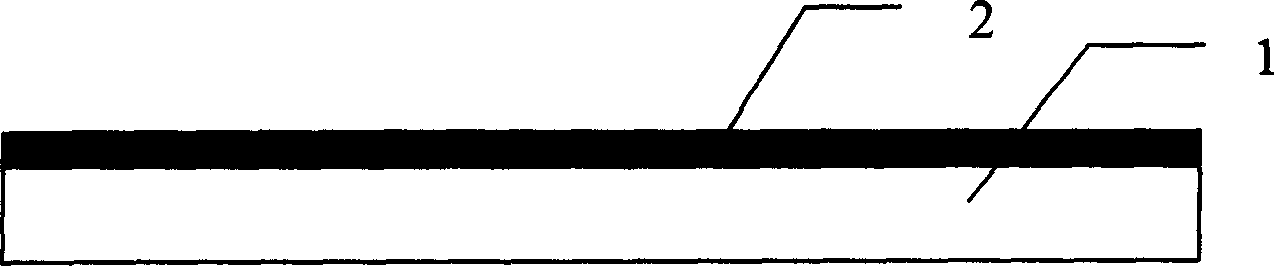
[0030] ① First determine the base material and the main etchant, as well as the material of the sacrificial layer and the auxiliary etchant. The material of the target component is metal: steel, so choose hydrochloric acid as the main etchant, sio 2 The membrane can be corroded with HF acid, usually with a concentration of 49%, while hydrochloric acid can coexist with HF, with a concentration of 49%. At the same time, hydrochloric acid does not corrode quartz, so sio 2 Membrane and HF acid meet the conditions of sacrificial layer and auxiliary etching solution, choose sio 2 As the sacrificial layer material, HF acid is selected as the auxiliary etching solution;

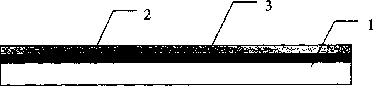
[0031] ② Evaporate a certain thickness on the surface of the base material, usually a 200nm sacrificial la...

Embodiment 2

[0037] Embodiment 2, make aperture φ=30 μ m, interval 700 μ m (total 5), the quartz material micro grating array of etching depth h=70 μ m, its manufacturing process is as follows:

[0038] ① First determine the base material and the main etchant, as well as the material of the sacrificial layer and the auxiliary etchant. The material of the target element is fused silica, so HF solution is selected as the main etchant. Silver Ag film can be treated with HNO 3Corrosion, while nitric acid can coexist with HF solution, at the same time, nitric acid HNO 3 Does not corrode quartz, so silver Ag and HNO 3 Meet the conditions of the sacrificial layer and auxiliary etching solution, choose silver as the material of the sacrificial layer, choose HNO3 3 as an auxiliary etchant;

[0039] ② Evaporate a certain thickness on the surface of the base material, usually 200nm sacrificial layer material silver Ag;

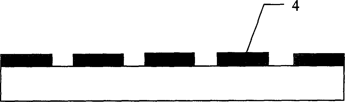
[0040] ③ Coating a layer of photoresist on the surface of the sacrificial l...


PUM

PropertyMeasurementUnit
thicknessaaaaaaaaaa
thicknessaaaaaaaaaa
depthaaaaaaaaaa

Abstract

The invention discloses a forming method of wet lateral guiding lenticular, which is characterized by the following: depositing the sacrificial layer on the base material surface; coating the photoresist on the sacrificial layer surface; affirming the base plate surface position of lenticular; adapting photoetching process to remove the photoresist except lenticular caliber scale if the lenticular displays compact distribution; regarding several transverse micrometer scales of the lowest lenticular as opening; removing the corrosion-proof agent in the opening scale; adapting the auxiliary photoresist to remove the exposed sacrificial layer; blending the main etching liquid and auxiliary etching liquid in proportion; placing the removed structure to be corroded in the mixing liquid; cleaning the element; drying the element.

Description

technical field [0001] The invention relates to a method for manufacturing a microlens array with high resistance to damage, in particular to a method for forming a microlens array by a wet method side guide. The method can realize the formation of microcolumn lens arrays made of various materials such as quartz and glass. Background technique [0002] The fabrication method of continuous relief microlens array has been a research hotspot all the time. The existing microlens array processing methods include photolithography thermal melting method, gray mask method, moving mask method, laser direct writing method, etc., see Micro-optical components, systems and applications, written by HANS PETER HERZIG in Switzerland, translated by Zhou Haixian, etc. The above-mentioned methods are mainly used to shape the microstructure of the resist material. In order to obtain micro-elements that can be used in practice, it is usually necessary to use ICP dry etching to convert the resis...

Claims


Application Information

Patent Timeline
Patent Type & Authority Applications(China)
IPC IPC(8): G02B3/00G03F7/20G03F7/32
Inventor 董小春杜春雷刘强李淑红邓启凌
Owner INST OF OPTICS & ELECTRONICS - CHINESE ACAD OF SCI
Why Eureka
Try Eureka