Capping technology for electron beam physical gaseous phase deposition coating using strong flow pulse ionic beam

A technology of physical vapor deposition and high-current pulse, which is applied to coatings, electrical components, ion implantation plating, etc., can solve the problems of reducing thermal fatigue resistance of coatings, increasing the complexity and cost of capping process, and inducing stress concentration. Achieve the effects of improving thermal corrosion resistance, high temperature oxidation resistance and prolonging service life

Inactive Publication Date: 2007-04-18
DALIAN UNIV OF TECH
View PDF2 Cites 9 Cited by
  • Summary
  • Abstract
  • Description
  • Claims
  • Application Information

AI Technical Summary

Problems solved by technology

[0007] The above-mentioned methods for establishing the capping layer have the following disadvantages: ① penetrating cracks and high-density cracks in the molten layer are inevitable in laser remelting; ② the capping process can only be completed by continuous multiple scanning, and the auxiliary process is needed to establish Relatively dense topping layer, thus increasing the complexity and cost of the topping process; ③The high densification of phosphate and sol-gel topping layers will induce stress concentration and reduce the thermal fatigue resistance of the coating
[0008] The processes of laser remelting and phosphate and sol-gel capping methods to establish capping layers are all applied to plasma sprayed coatings with lamellar structure, while for electron beam physical vapor deposition coatings with columnar crystal structure modification has not been reported

Method used


Image

  • Capping technology for electron beam physical gaseous phase deposition coating using strong flow pulse ionic beam
  • Capping technology for electron beam physical gaseous phase deposition coating using strong flow pulse ionic beam
  • Capping technology for electron beam physical gaseous phase deposition coating using strong flow pulse ionic beam

Examples


Embodiment 1

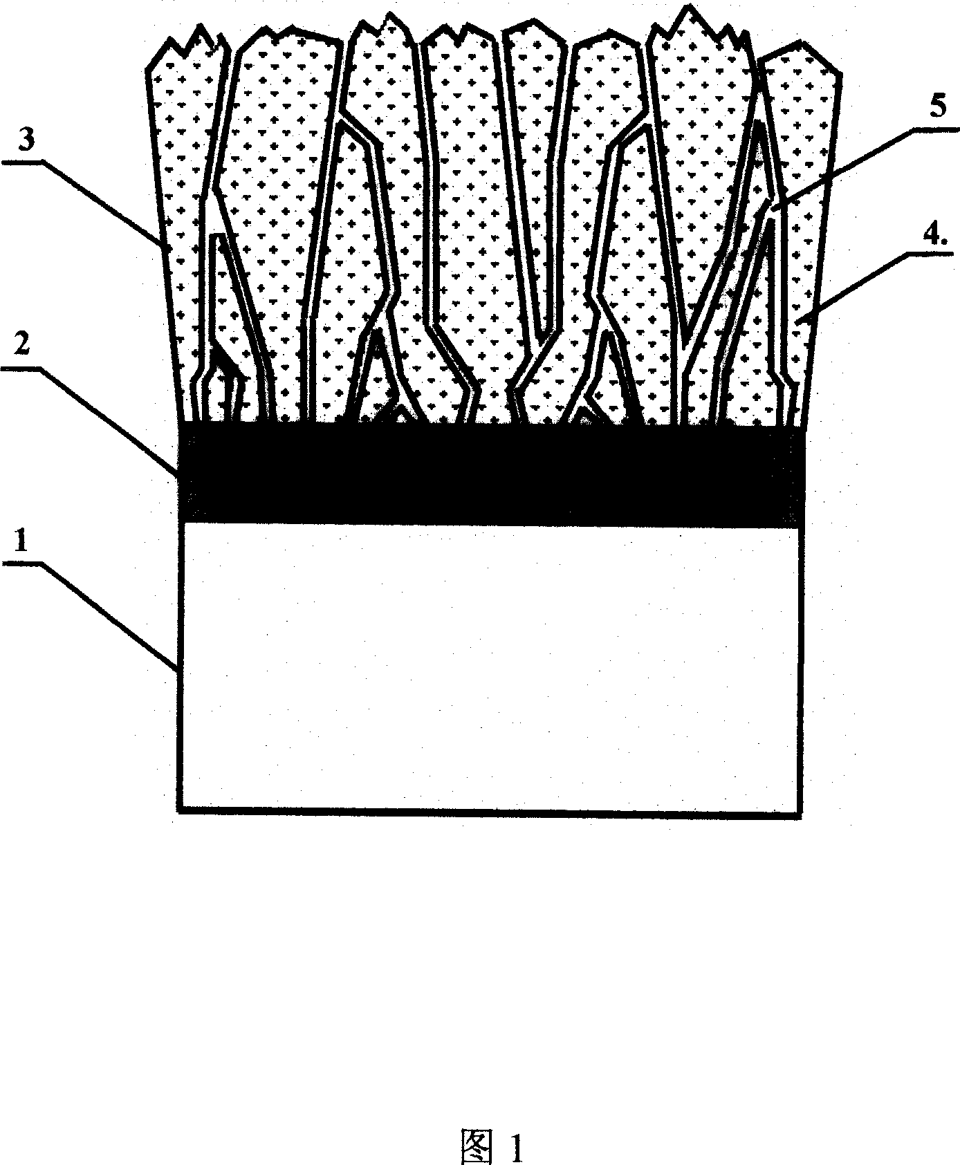
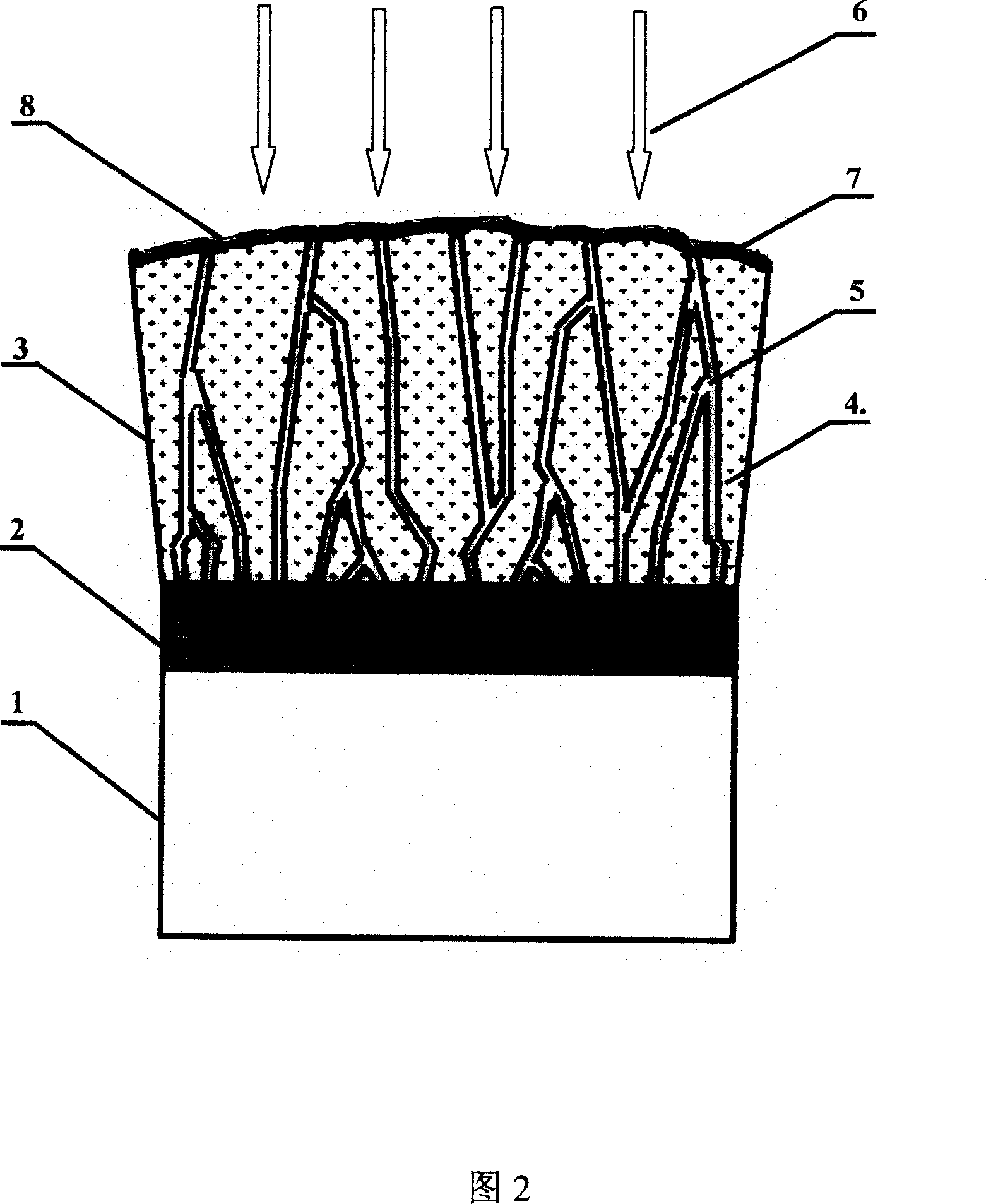
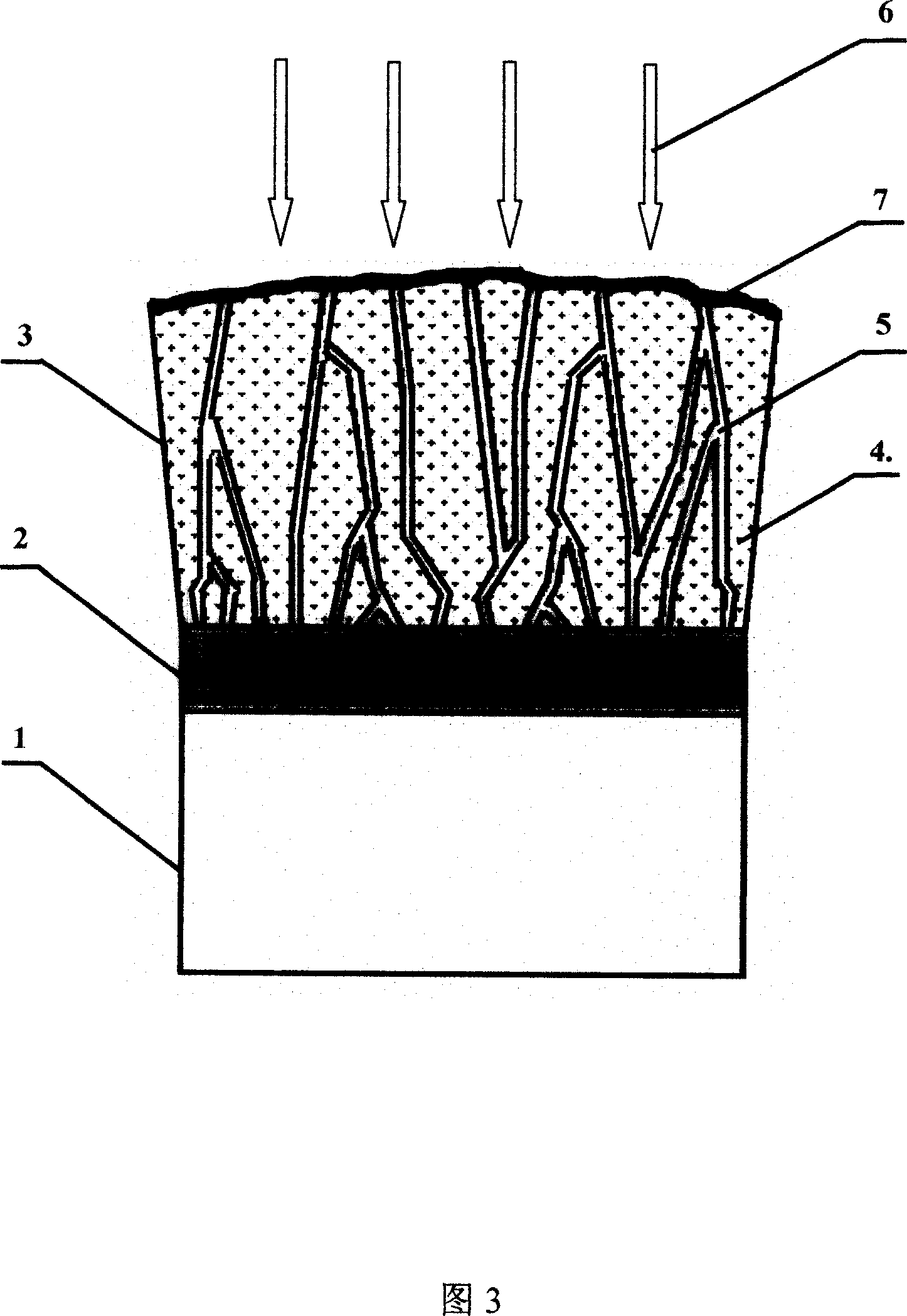
[0044] After an aero-engine company adopts electron beam physical vapor deposition coating on the blades of a gas turbine engine, it is required to form a 1 μm thick continuous tight top layer 7 on the surface of the ceramic layer 3, and the surface of the coating after treatment is required to be flat and smooth, so as to improve coating performance. The high temperature oxidation resistance and thermal shock performance of the layer. Now adopt the inventive method, its capping process step is as follows:

[0045] In the first step, the turbine blade is placed on the sample stage and vacuumized

[0046] Place the turbine blade with the deposited metal bonding layer and ceramic layer on the sample stage of the high-current pulsed ion beam device, so that the surface of the ceramic layer on the front surface of the blade is completely exposed to the high-current pulsed ion beam irradiation area, and close the The vacuum chamber of the device is evacuated, and its vacuum degree...

Embodiment 2

[0054] A company requires that the coated guide vane be capped, and a continuous tight sealing top layer 7 with a thickness of 3 μm is required to be formed on the surface of the ceramic layer 3 to improve the high temperature oxidation resistance of the guide vane, and the treated coating surface is required to be smooth. To reduce the resistance of the guide vanes to the gas, the method of the present invention is now adopted, and its capping process steps are as follows:

[0055] The first step is to place the guide vanes on the sample stage and vacuumize

[0056] Place the guide vane with deposited metal bonding layer and ceramic layer on the sample stage of the high-current pulsed ion beam device, so that the surface of the guide vane ceramic layer is completely exposed in the high-current pulsed ion beam irradiation area, and close the device The vacuum chamber is evacuated, and its vacuum degree reaches 1.0×10 -2 Pa.

[0057] The second step is to establish a capping ...

Embodiment 3

[0064] A diesel engine production unit wants to cap the coated diesel engine piston, and requires a continuous sealing top layer 7 with a thickness of 5 μm on the surface of the ceramic layer 3 to improve the high temperature oxidation resistance and thermal corrosion resistance of the piston. Chamber heat loss, now adopt the method of the present invention, its capping process steps are as follows:

[0065] The first step is to place the piston on the sample stage and vacuumize

[0066] Place the diesel engine piston with deposited metal bonding layer and ceramic layer on the sample stage of the high-current pulsed ion beam device, so that the surface of the piston ceramic layer is completely exposed in the high-current pulsed ion beam irradiation area, and close the device. The vacuum chamber is evacuated, and its vacuum degree reaches 8×10 -3 Pa.

[0067] The second step is to establish a capping layer on the surface of the piston ceramic layer

[0068] At room temperatu...


PUM


Abstract

In the field of material surface modifying, using high-current pulsed ionizing beam to plug electron-beam physical vapour deposition coat. The method contains parts base resisting to elevated temperatures 1, surfacial plated metal tack coat 2, ceramic coat 3 and plugging coat 7 on 3. It is characterized in that: Under vacuum degree of 0.8-1.1*10-2Pa, high-current pulsed ionizing beam with beam density of 250-350A / cm2 is adopted to irradiate and form 7 on the surface of 3, which close crystal gap 5 used as oxide diffusing channel between columnar grains 4. High-current pulsed ionizing beam with beam density of 50-100A / cm2 is used to seam micro-cracks 8 on the surface of 7. strongpoint: simple craft, realizing continuous compact 7 with required thickness by irradiating less times, without penetrability macro-crack, surface of 7 is slick and plat, after plugging, non-oxidization of electron-beam physical vapour deposition coat can be improved over 2 times.

Description

technical field [0001] The invention relates to a capping technology of an electron beam physical vapor deposition coating on the surface of a high-temperature-resistant component by using a high-current pulsed ion beam, and belongs to the field of material surface modification. Background technique [0002] With the increase of gas temperature, high-heat components in the engine, such as turbine blades and guide vanes used in the aviation field, and pistons in ordinary engines, face a very harsh service environment. For example, the turbine blades in aero-engines are designed with superalloys with excellent high-temperature resistance and special cooling structures, but these parts are still prone to failure under high-temperature corrosion conditions, and their life is often the decisive factor for modern high-performance blades. Constraints on Jet Engine Performance. [0003] In recent years, as a barrier to isolate high-temperature and corrosive media, coatings provide ...

Claims


Application Information

Patent Timeline
Patent Type & Authority Applications(China)
IPC IPC(8): C23C14/58H01J37/305H01J37/317C23C14/24F01D5/28F02F3/10
Inventor 雷明凯刘臣信敬平韩晓光朱小鹏
Owner DALIAN UNIV OF TECH
Why Eureka
Try Eureka