High density thermal storage arrangement

a high-density, thermal storage technology, applied in the direction of heat storage plants, driver interactions, railway components, etc., can solve the problems of increasing fossil fuel costs, threatening the economies of nations forced to import much of their energy, and threatening global trade and transportation, so as to reduce the surface erosion

Active Publication Date: 2019-07-09
KELVIN THERMAL ENERGY INC
View PDF10 Cites 17 Cited by
  • Summary
  • Abstract
  • Description
  • Claims
  • Application Information

AI Technical Summary

Benefits of technology

[0026]According to an aspect of the invention the partial channels include a suitable surface coating to reduce surface erosion of the opposed partial channels of the graphite blocks.

Problems solved by technology

Rising fossil fuel costs driven by continuously increasing global energy demand, coupled with progressively more challenging access to reducing planetary fossil fuel reserves, not only threaten the economies of nations forced to import much of their energy, but also threaten global trade and transportation.
Upon arriving at destinations, their crude oil must be piped to refineries and the resulting products are then typically trucked to points of use—all stages consume energy and emit air pollutants and in particular, the crude oil tankers are amongst the heaviest air polluters in the world.
For example, in the case of electrical generation via the consumption of fossil fuels and other combustibles, these feed stocks are typically shipped to generation facilities and burned as close as possible to demand centers with the downside of municipal air quality degradation.
However, as the percentage of such generation to overall electrical generation on any given continental grid grows, it poses two key challenges to distribution systems: 1) It is often not possible to locate such facilities within close proximity to demand centers; and, 2) Most renewable sources other than geothermal (which is only commercially feasible in limited areas of the planet), produce at intermittent periods which often do not coincide with demand.
This table details the stored energy density—but in the case of combustible or thermal sources (Gasoline, Rocket Fuel and Thermal Graphite Storage), not what can be effectively utilised as electricity with current energy conversion methods.
For example, although Gasoline's energy density is listed as 5,500 kWh / ton, when Gasoline is combusted in an internal combustion engine driving an electric generator, only a small portion of its energy potential is ultimately available as electric energy since much of the stored energy is lost in the conversion process as waste heat.
Net energy from various chemical / battery storage technologies is impacted by cell life, temperature, discharge rates, and the performance of other inter-connected cells—also dropping effective output from that predicted by ideal conditions in the table.
Energy stored in strategically located thermal-graphite systems may then be converted, via a host of available systems (broadly classified as heat engines which typically turn heat into mechanical motion necessary to drive electrical generators—such engines span from large supercritical steam turbines to small Stirling engines) to electrical energy on-demand, meeting electrical demand peaks and smoothing production drops typical of renewable generation, but also due to unexpected failures of conventional nuclear and hydrocarbon powered generating facilities.
Unfortunately there remains the obvious requirement, common to all storage systems, for the critical provision of a suitable recharging period.
Without such periods, storage systems are not recharged, and have less capacity to support the grid during times of low or zero renewable energy production.
And unlike fossil fuels, when there is a shortage of renewable resources, there is no effective global transportation system which can move renewable energy to areas of need.
However, since such on-demand reserves are powered by fossil fuels, even with current fossil fuel global shipping operations, their availability in the future is uncertain in light of dwindling planetary fossil fuel reserves and increasing concerns about the air pollutants emitted during combustion of such fuels.
Furthermore, powering spinning reserves with fossil fuels competes with the need for fossil fuels to be used for plastics and to power aircraft—both uses have no apparent substitutes and will thus pay whatever the cost to ensure priority supply.
1) Latitude dependent, seasonal reductions in solar and / or wind energy
2) Periodic prolonged periods of little or no wind or continued cloud
3) Massive storm centers which not only block solar energy, but exceed the wind tolerances of wind turbines, concurrently eliminating both forms of renewable energy
4) Environmental and equipment disasters leading to grid connectivity failures
5) Shortage of available land area for solar and / or wind installations of sufficient output to guarantee surplus charging periods
6) Failure of nuclear or other generation due to equipment breakdown or earthquake related events
7) Failure of grid infrastructure to expand with energy demand
8) Accelerated adoption of electric ground transportation—such vehicles, typically choosing to recharge at off-peak periods, reducing and possibly eliminating any available surplus
There remains a need for grid support in periods, and at specific places, where the reduction or elimination of such recharging periods renders local storage systems inoperative and leaves the renewable-powered grid unstable.

Method used


Image

  • High density thermal storage arrangement
  • High density thermal storage arrangement
  • High density thermal storage arrangement

Examples


Embodiment Construction

[0041]Renewable and sustainable energy, typically in the form of electrical energy, may be reliably produced for export / transport, depending on geography and climate conditions from solar, wind and geothermal sources. For example, Iceland has year-round sustainable geothermal energy production and in the sunny arid portions of Africa, plenty of land is available with year-round sun, for solar renewable generation.

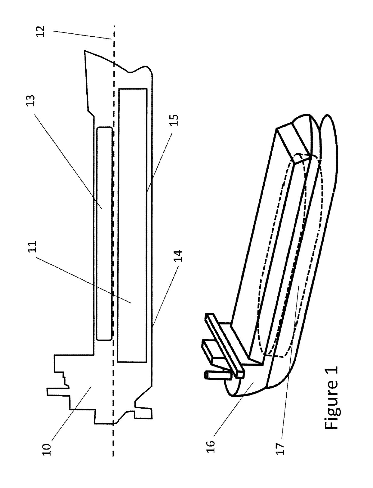
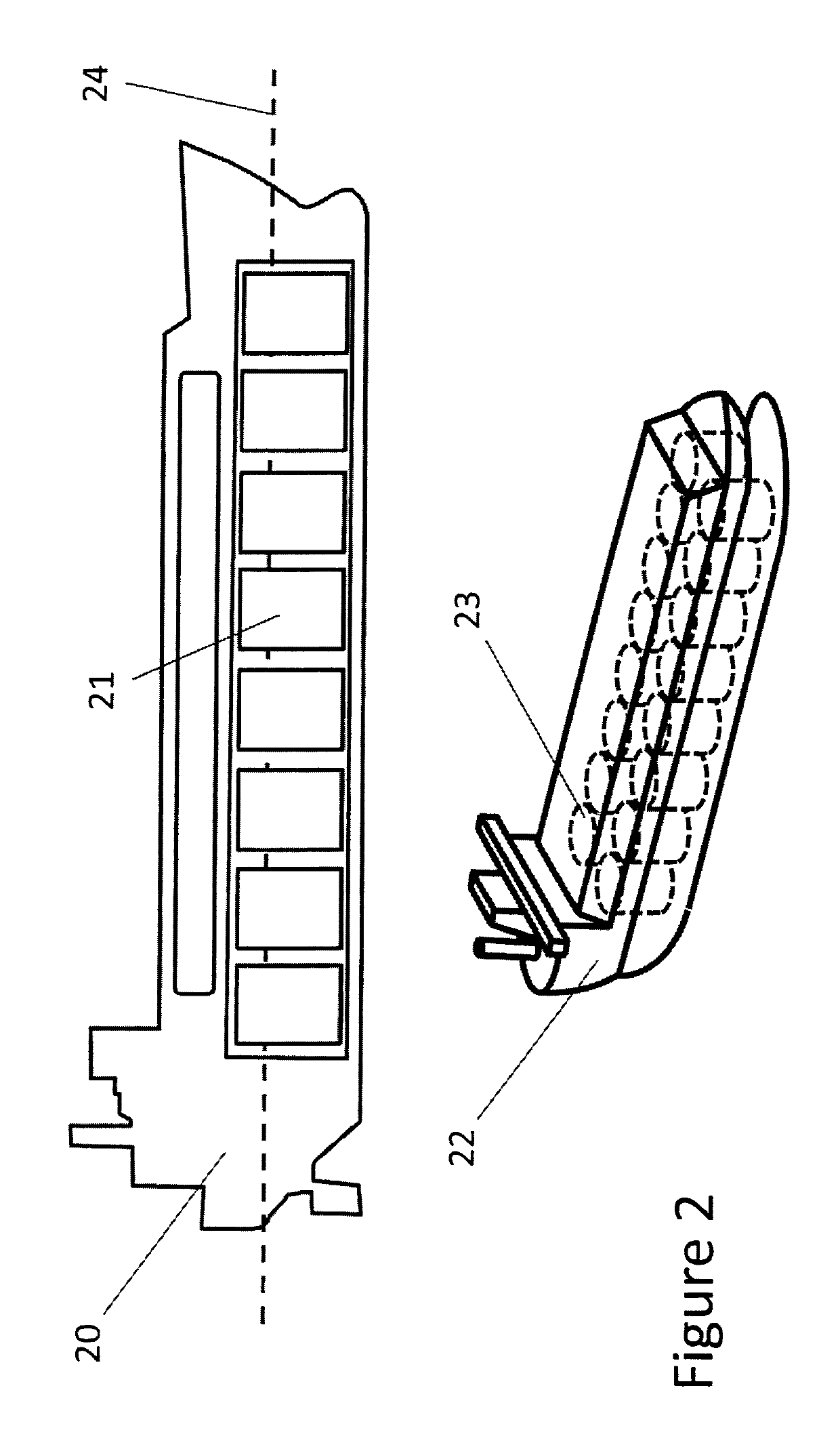
[0042]A fleet or network of energy transport ships 10 illustrated in FIG. 1 are built to store and transport renewable and sustainable energy containing permanently installed containment modules 11. Each module may be a single integral containment module that is designed to remain as part of the ship. Each containment module houses a graphite core typically consisting of a series of graphite bundles which preferably sits below the waterline 12 to increase ship stability to minimise motion which could damage such core. The ships also contain operating facilities 13 which inc...


PUM


Abstract

An energy transportation and grid support system utilizes at least one transportable containment module capable of storing thermal or chemical energy typically produced from renewable or geothermal sources and providing connectivity with energy conversion equipment typically located in a land or sea-based operating facility. The system includes circuitry to hookup to an adjacent electricity grid for the provision of grid support and / or piping to move thermal energy typically used to drive steam turbines generating ′ electricity. The operating facility also includes a communication arrangement to link with and exchange operations control data with a grid or heating operator and the energy transportation operator. The invention is directed to both apparatus and method for the energy transportation and grid support system.

Description

FIELD OF THE INVENTION[0001]The present invention relates to thermal energy storage using a graphite core. Effective thermal energy storage has particular application with respect to transportation and distribution of energy, stationary energy storage, electrical grid stabilization, and electrical transmission systems.BACKGROUND OF THE INVENTION[0002]Even the most optimistic forecasters of global energy supplies are concerned about the possible adverse societal effects of energy scarcity and rationing in the foreseeable future. Unless sustainable (ie: geothermal) and renewable (ie: wind, solar) energy production grows to meet a very significant portion of global energy demand within this century, every country will be impacted by energy scarcity in the coming years. Rising fossil fuel costs driven by continuously increasing global energy demand, coupled with progressively more challenging access to reducing planetary fossil fuel reserves, not only threaten the economies of nations f...

Claims


Application Information

Patent Timeline
Patent Type & Authority Patents(United States)
IPC IPC(8): F28D20/02H02M7/217B60L7/14B60L7/22B61H9/06B60L7/06F28D20/00B60L1/02H02S10/20B60T1/10B60T13/58F28F21/02
CPCF28D20/021B60L7/06B60L7/14B60L7/22B60T1/10B60T13/586B61H9/06F28D20/0056H02M7/217H02S10/20B60L1/02Y02T90/16B60L2200/26B60L2210/40B60L2250/12B60L2250/16F28D2020/0082F28F21/02Y02E60/142Y02E70/30Y02T10/7241F16D61/00Y02E10/50Y02E60/14Y02T10/72
Inventor PIETSCH, ANTONLYNCH, GEORGE W.SUTHERLAND, STEPHEN B.
Owner KELVIN THERMAL ENERGY INC
Why Eureka
Try Eureka