With such widely utilized power sources, however, comes certain problems, some of which have proven increasingly serious.
Notably, safety issues have come to light wherein certain imperfections within such lithium batteries, whether due to initial manufacturing issues or time-related degradation problems, cause susceptibility to firing potentials during
short circuit events.
Basically, internal defects with
conductive materials have been found to create undesirable
high heat and, ultimately, fire, within such battery structures.
Even the Tesla line of
electric cars have exhibited notable problems with
lithium battery components, leading to headline-grabbing stories of such expensive vehicles exploding as fireballs due to battery issues.
These problems primarily exist due to manufacturing issues, whether in terms of individual battery components as made or as such components are constructed as individual batteries themselves.
However, as alluded to above, certain events and, in particular, certain defects can cause internal shorting between the internal
conductive materials which can lead to
heat generation and internal
thermal runaway, known to be the ultimate cause of fire hazards within such lithium batteries.
Such events may further be caused by, as noted above, internal defects including the presence of metallic particles within the battery, burrs on the
current collector materials, thin spots or holes in the separator (whether included or caused during subsequent
processing), misalignments of battery
layers (leaving “openings” for unwanted
conductivity to occur), external debris penetrating the battery (such as
road debris impacting a moving vehicle), crushing and / or destabilizing of the
cell itself (due to accidents, for instance), charging the
cell in a
confined space, and the like.
Generally speaking, these types of defects are known to cause generation of a small electronic conductive pathway between the
anode and
cathode.
When such an event occurs, if the
cell is then charged, such a conductive pathway may then cause a
discharge of the cell therethrough which ultimately generates excessive heat, thereby compromising the battery structure and jeopardizing the underlying device being powered thereby.
Combined with the presence of flammable
organic solvent materials as battery electrolytes (which are generally of necessity for battery
operability), such excessive heat has been shown to cause ignition thereto, ultimately creating a very dangerous situation.
Such problems are difficult to control once started, at the very least, and have led to significant injuries to consumers.
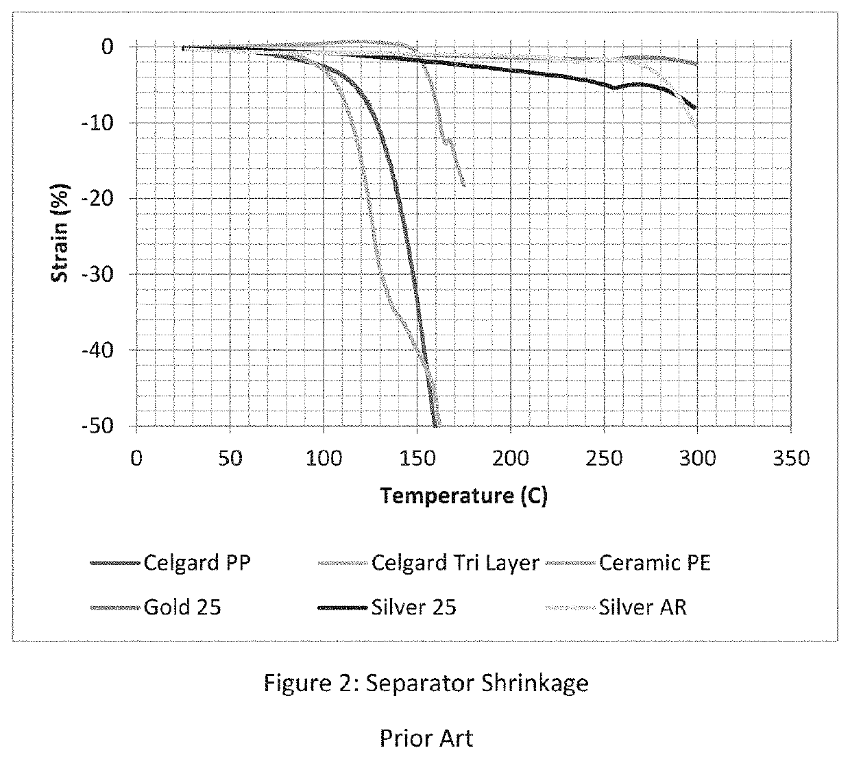
The generation of excessive heat internally may further create shrinkage of the plastic separator, causing it to move away from, detach, or otherwise increase the area of a short within the battery.
In such a situation, the greater exposed short area within the battery may lead to continued current and increased heating therein, leading to the high temperature event which causes significant damage to the cell, including
bursting, venting, and even flames and fire.
Such damage is particularly problematic as the potential for firing and worse comes quickly and may cause the battery and potentially the underlying device to suffer an explosion as a result, putting a user in significant danger as well.
Lithium batteries (of many varied types) are particularly susceptible to problems in relation to short circuiting.
Typical batteries have a propensity to exhibit increased
discharge rates with high temperature exposures, leading to uncontrolled (runaway) flaring and firing on occasion, as noted above.
The problem has remained, however, as to how to actually corral such issues, particularly when component production is provided from myriad suppliers and from many different locations around the world.
In actuality, though, the thermal increase imparted to the overall
film structure with
ceramic particle coatings has been found to be relatively low, thus rendering the
dominant factor for such a separator issue to be the actual separator material(s) itself.
Such
low shrinkage rate materials may change the mechanism of thermal degradation inside a target cell when a short occurs.
Once the circuit is broken, the current stops flowing and the heat is no longer generated, reversing the process that, with less stable separators, leads to
thermal runaway.
This possible solution, however, is limited to simply replacing the separator alone with higher
shrinkage rate characteristics.
Although such a simple resolution would appear to be of great value, there still remains other manufacturing procedures and specified components (such as
ceramic-coated separator types) that are widely utilized and may be difficult to supplant from accepted battery products.
Thus, despite the obvious benefits of the utilization and inclusion of thermally stable separators, undesirable battery fires may still occur, particularly when
ceramic coated separator products are considered safe for such purposes.
Until now, however, nothing has been presented within the
lithium battery art that easily resolves these problems.
As there have been no disclosures within the
lithium ion battery art regarding such thin film current collectors, there is likewise nothing that has attempted to improve upon or optimize such tab connection issues, either.
Certainly, standard types of tabs are well known and connect with large current collectors of standard battery cells; however, such do not provide any considerations as to protecting the effects of thin film current collectors (internal fuse, for instance) while still providing a dimensionally stable result overall to protect from battery failure due to structural compromises.
The present disclosure, however, overcomes such paradigms and provides a result heretofore unexplored and / or understood within the pertinent industry.
Within the present disclosure, while it may be possible to measure a larger current, the delivery time for such a current is sufficiently short such that the
total energy delivered is very small and not enough to generate enough heat to cause a
thermal runaway event within the target
battery cell.
This
resultant measurement can increase the temperature of a 1-
gram section of the subject battery by about 300° C., a temperature high enough to not only melt the conventional separator material present therein, but also drive the
entire cell into a runaway thermal situation (which, as noted above, may cause the aforementioned compromise of the
electrolyte materials present therein and potential destruction of not only the subject battery but the device / implement within which it is present and the surrounding environment as well.
Such a novel
current collector component is actually counterintuitive to those typically utilized and found within lithium (and other types) of batteries and
energy storage devices today.
It appears, however, that such a belief has actually been misunderstood, particularly since the thick panels prevalent in today's
energy storage devices will actually not only arc when a short occurs but contribute greatly to runaway temperatures if and when such a situation occurs.
Such a malformation (whether caused at or during manufacture or as a result of long-term usage and thus potential degradation) may allow for
voltage to pass unexpectedly from the
anode to the
cathode, thereby creating an increase in current and consequently in temperature at the location such occurs.
Indeed, one
potential source of
short circuit causing defect are burrs that form on the edges of these thick typical current collectors when they are slit or
cut with worn blades during repetitive manufacturing processes of multiple products (as is common nowadays).
It has been repeatedly analyzed and understood, however, that the standard
current collector materials merely exhibit a propensity to spark and allow for temperature increase, and further permitting the current present during such an occurrence to continue through the device, thus allowing for unfettered generation and movement, leaving no means to curtail the current and thus temperature level from increasing.
This problem leads directly to runaway high temperature results; without any internal means to stop such a situation, the potential for fire generation and ultimately device immolation and destruction is typically imminent.
With a
short circuit, however, this current pathway fails to prevent or at least curtail or
delay such charge movement, allowing, in other words, for rapid
discharge in runaway fashion throughout the battery itself.
Coupled with the high temperature associated with such rapid discharge leads to the catastrophic issues (fires, explosions, etc.) noted above.
In other words, with the particular structural limitations accorded the disclosed current collector component herein, the
current density increases to such a degree that the resistance level imparts an extremely high, but contained, high temperature occurrence in relation to a short circuit.
With such instantaneous nonconductive material generation, the short circuit charge appears to dissipate as there is no direction available for movement thereof.
Thus, with the current collector as now described, an internal short circuit occurrence results in an immediate cessation of current, effectively utilizing the immediate high temperature result from such a short to generate a barrier to further charge movement.
Thus, the entire current collector, due to its
instability under the conditions of a short circuit, becomes a two-dimensional electrical fuse, preventing the potentially disastrous high currents associated with short circuits by using the instantaneous effect of that
high current to destroy the ability of the current collector to conduct current at the point of the short circuit.
Typical current collectors may exhibit these features but do so at far higher weight than those made with reinforcing polymeric substrates and without the
inherent safety advantages of this presently disclosed variation.
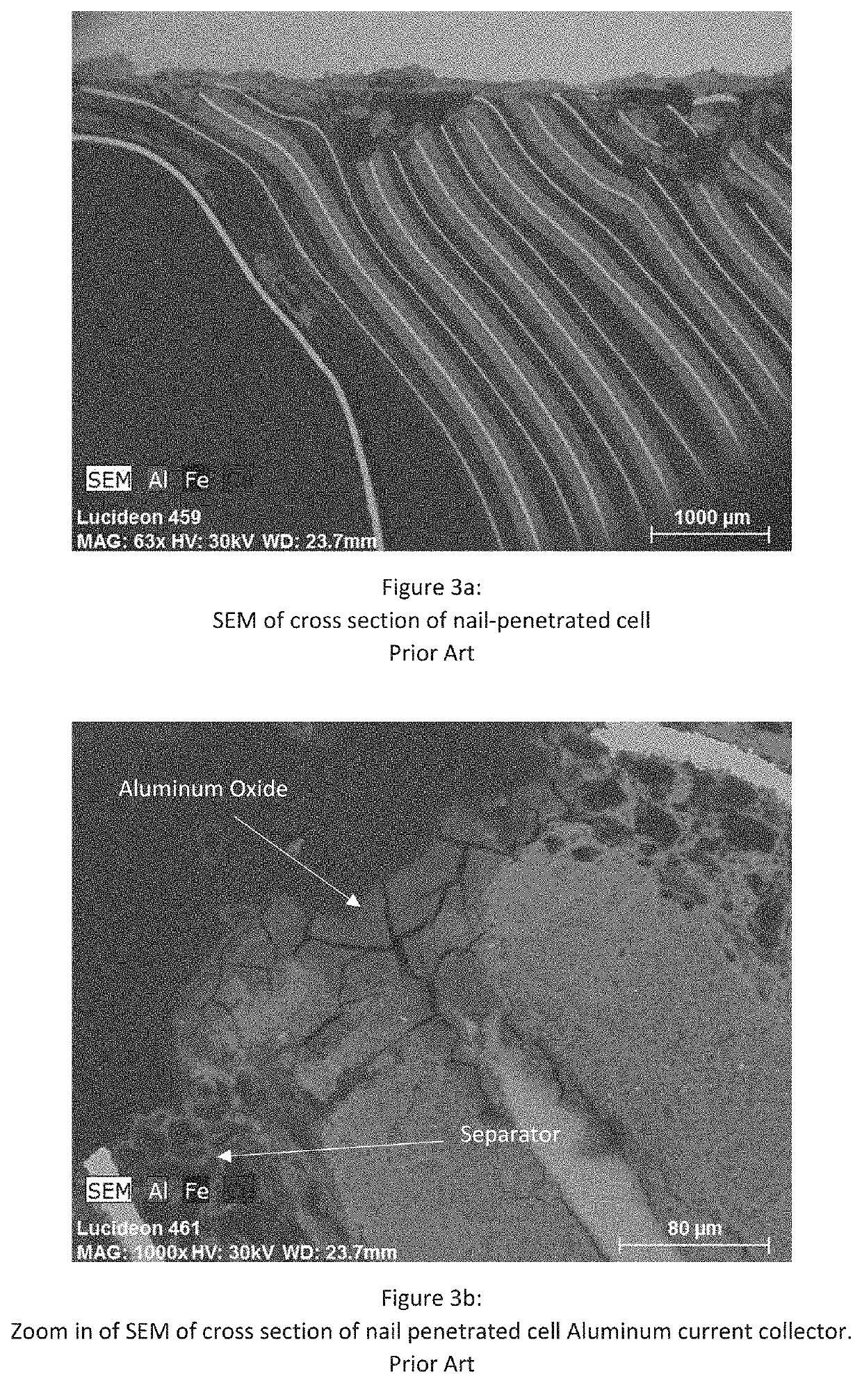
In this alternative structure, however, the very thin component also allows for a short to react with the
metal coat and in relation to the overall resistance levels to generate, with an excessively high temperature due to a current spike during such a short, a localized region of
metal oxide that immediately prevents any further current movement therefrom.
Certain alloys of aluminum will oxidize faster than aluminum itself, and these alloys would cause the conductive pathway to deteriorate faster or at a lower temperature.
Such a result is not possible for a non-coated
polymer film, for instance.
Again, it is completely counterintuitive to utilize thin metallized coated polymeric
layers, particularly of low dimensionally stable characteristics, for current collectors within such battery articles.
In this way, the bulk
conductivity can be provided by the aluminum, which is light, in expensive and can easily be deposited by
vapor phase deposition techniques.
However, the
porosity must not be too high for these materials, as such would result in low strength and high thickness, effectively defeating the purpose of the goals involved.
The current collector utilized herewith and herein, however, is, as disclosed, not only new and unexplored within this art, but counterintuitive as an actual
energy storage device component.
In essence, the heat generated at the prior art current collector causes the initial electrochemical reactions within the
electrolyte materials, leading, ultimately to the uncontrolled ignition of the
electrolyte materials themselves.
Such electrolytes are preferred within the battery industry, but, as noted, do potentially contribute to dangerous situations.
As noted above, the ability to determine proper dimensions of both current collector film(s) and tabs with suitable welds for effective attachment and contact for
electrical current to pass through effectively for battery operation, while still exhibiting the proper low potential for runaway charge has proven difficult, particularly in view of the specific and accepted thick monolithic current collector components of the state of the art today.

