Method of drying copper foil and copper foil drying apparatus

a drying apparatus and copper foil technology, applied in drying machines with progressive movements, lighting and heating apparatus, furnaces, etc., can solve the problems of large space required, large size of the apparatus, and large energy loss attributed to discharged hot air, and achieve high energy efficiency, easy absorbing, and improved acid resistance

Inactive Publication Date: 2001-11-29
IMADA NOBUYUKI +1
View PDF0 Cites 5 Cited by
  • Summary
  • Abstract
  • Description
  • Claims
  • Application Information

AI Technical Summary

Benefits of technology

[0065] In the present invention, the near infrared rays with which the copper foil surface is irradiated to thereby dry the copper foil are easily absorbed by the copper foil surface, so that the copper foil surface can be heated to a given temperature with a high energy efficiency. Moreover, the copper foil surface can be heated and regulated at a given temperature by changing voltage and electric current outputs applied to the unit irradiating near infrared rays.[0066] As a result, the copper foil surface can be heated and dried at 100.degree. C. or higher at which the alloying (brass formation) of zinc-copper occurs, so that not only is the acid resistance improved but also, the bonding strength with a resin substrate is increased to provide increased peel strength and avoid separation of the copper foil from the resin substrate.[0067] The surface of the copper foil exhibits a low absorption of far infrared rays, so that the energy loss is large. Much time and energy must be spent for raising the temperature to a given level and, because of poor efficiency, the apparatus must be large and the residence time of the copper foil therein must be prolonged. Further, the hot air drying also exhibits poor energy efficiency and must be equipped with a heater, a blower and circulation paths including a path for discharging a large volume of exhaust gas containing steam outside the apparatus. Therefore, unfavorably, the size of the apparatus is large, the installation space thereof is large, and the cost is high. With respect to energy efficiency and quick response, the drying method using near infrared rays is strikingly superior to the above far infrared ray and hot air methods.[0068] Therefore, the present invention is remarkably excellent in view of the many effects including the compact apparatus, high energy efficiency, capability of heating and drying the copper foil surface at a given temperature, enhancement of acid resistance and production of copper foil exhibiting a high bonding strength when bonded with a resin substrate.

Problems solved by technology

However, this method relies on the heating (drying) through the heat transfer from hot air, so that the energy loss attributed to discharged hot air is large.
Therefore, unfavorably, the size of the apparatus is large, the space required is large, and the cost is high.
Therefore, the energy loss is large, and the temperature of the surface of the copper foil cannot be readily increased.
Accordingly, a multiplicity of far infrared ray irradiating units must be arranged for attaining temperatures of 130.degree. C. or higher, thereby resulting in disadvantages in terms of apparatus, power consumption and cost.

Method used


Image

  • Method of drying copper foil and copper foil drying apparatus
  • Method of drying copper foil and copper foil drying apparatus
  • Method of drying copper foil and copper foil drying apparatus

Examples


example 1

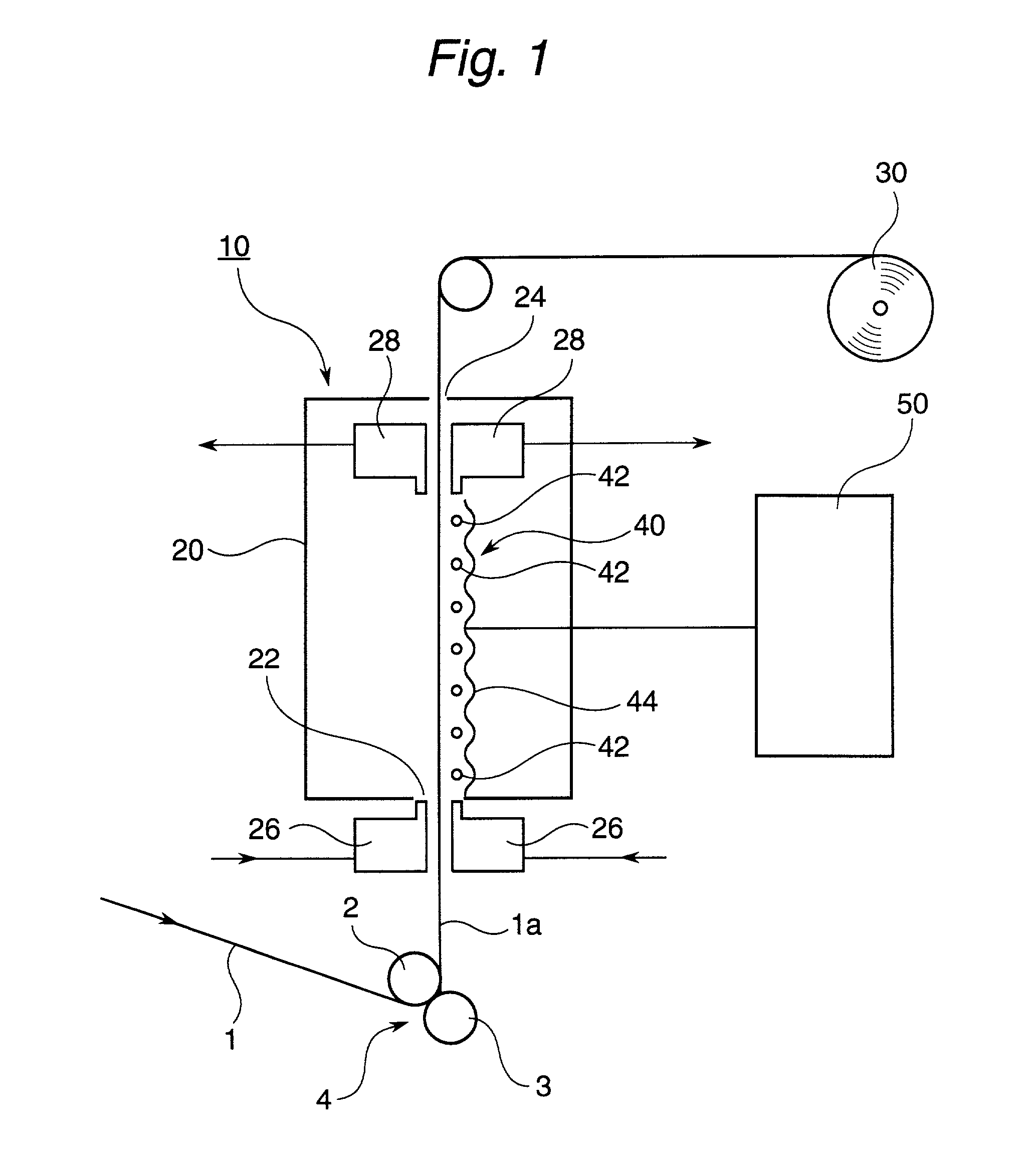
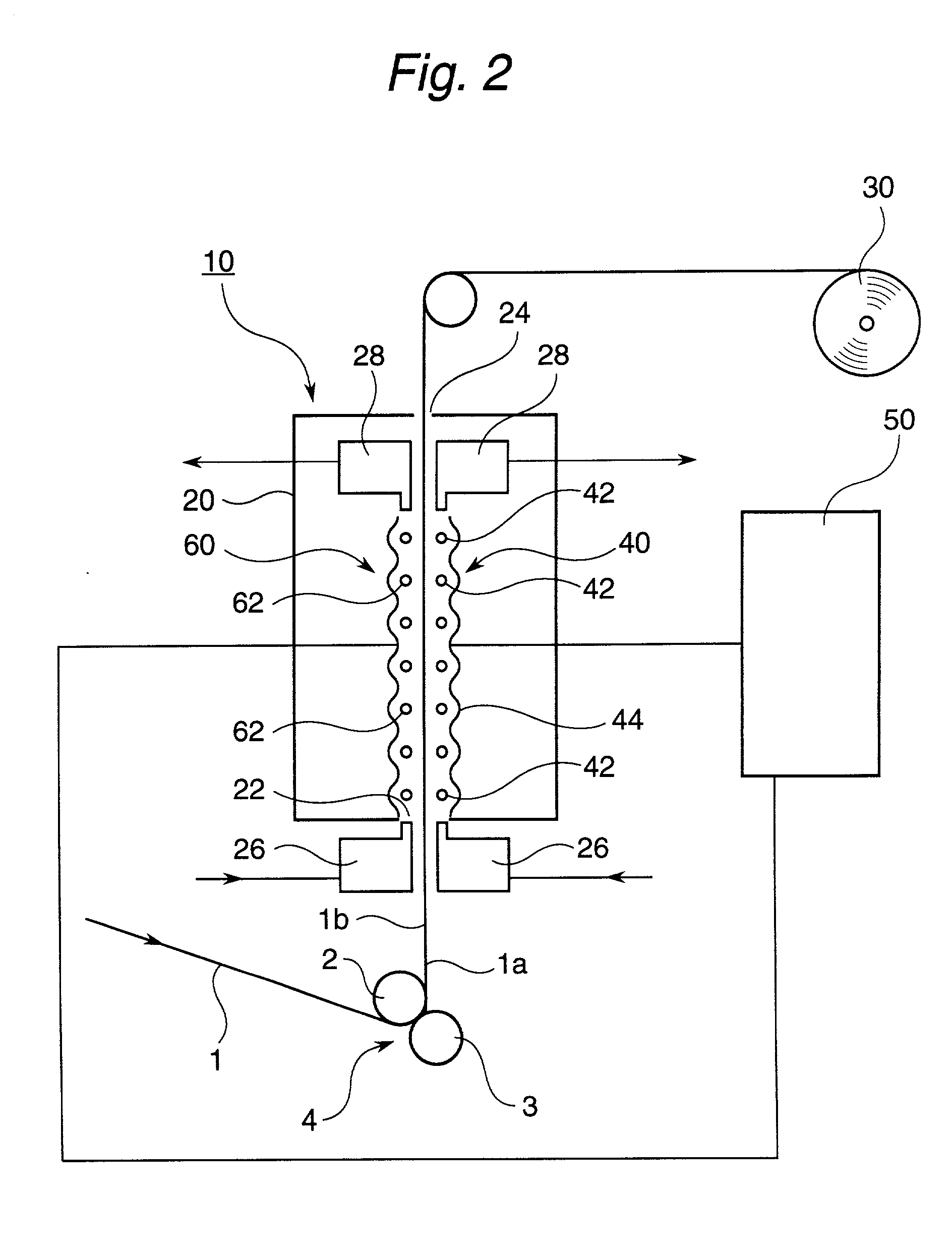
[0070] Electrodeposited copper foil having a thickness of 35 .mu.m was electrolyzed in an acidic copper sulfate solution so that the electrodposited copper foil was provided with copper plating to roughen the matte side of the electrodeposited copper foil. Thus, the copper foil having its matte side overlaid with a particulate copper layer was obtained (nodularization).

[0071] The resultant copper foil was electrolyzed in a zinc solution bath of pH 11.0 containing 10 g / L. of zinc pyrophosphate and 100 g / L. of potassium pyrophosphate at room temperature at a current density of 5 A / m.sup.2 for 6 sec so that the copper foil on its matte side was overlaid with 400 mg / m.sup.2 (in terms of zinc) of a zinc plating.

[0072] Subsequently, the zinc plated copper foil was electrolyzed in a chromating solution of pH 10 containing 2 g / L. of chromic acid at room temperature at a current density of 0.5 A / m.sup.2 for 5 sec so that the copper foil surface on its matte side was overlaid with a chromate ...

example 2

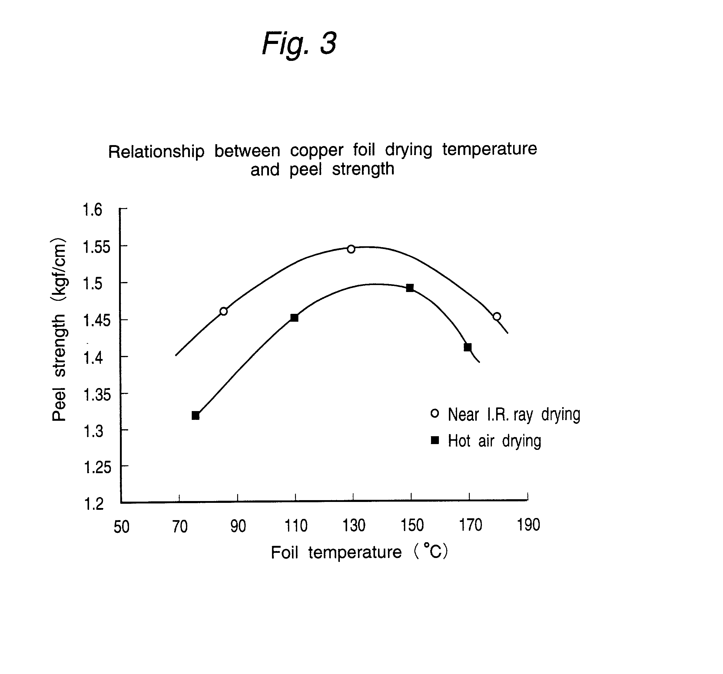
[0080] With respect to the energy required for raising the temperature of the surface of the copper foil after dewatering obtained in the same manner as in Example 1 to given level, near infrared ray, far infrared ray and hot air drying were compared to each other in the power and time spent for raising the temperature of the surface of the copper foil to given level. The results are given in Table 1 and FIG. 4.

1 TABLE 1 Index of electric energy (KWH / t) for increasing foil temp. to 130.degree. C. Near I.R. ray drying 100 Far I.R. ray drying 350 Hot air drying 250

[0081] As apparent from the results of FIG. 4, in the comparison of the time spent for raising the temperature of the surface of the copper foil to 130.degree. C., the time was only 1 sec when near infrared ray drying was used while about 15 sec was needed when far infrared ray drying was used although the far infrared heater had the same capacity as that of the near infrared heater.

[0082] Further, as apparent from the resul...

example 3

[0083] Copper foils produced by drying after dewatering in the same manner as in Example 1 with the use of near infrared rays at varied copper foil surface drying temperatures were hot-pressed to glass epoxy substrates, etched in 0.8 mm width and immersed in a 12% hydrochloric acid solution at room temperature for 30 min to thereby compare the acid resistances thereof with each other.

[0084] For comparison, the copper foils were dried by hot air at the same varied drying temperatures, and the acid resistances thereof were compared with each other.

[0085] The results are given in Table 2 below.

2 TABLE 2 Peel loss after Drying temp. (.degree. C.) HCL (%) Near I.R. ray 1 85 21 drying 2 110 6 3 150 0 4 170 12 Hot air drying 5 85 22 (Comp.) 6 110 10 7 150 6

[0086] It is apparent from the results of Table 2 that the hydrochloric acid resistance (improvement of peel loss after HCL) is enhanced by near infrared ray drying conducted with the drying temperature of the surface of the copper foil ...


PUM

PropertyMeasurementUnit
temperatureaaaaaaaaaa
wavelengthaaaaaaaaaa
temperatureaaaaaaaaaa

Abstract

A method employed to dry a copper foil having been subjected to various surface treatments, which method comprises irradiating at least one surface-treated side of the copper foil with near infrared rays to dry the copper foil, and an apparatus suitable to the method. The drying of the copper foil having undergone surface treatments can be accomplished by a simple apparatus with low electric power while controlling the heating of the surface of the copper foil so that the drying temperature can be held at 100° C. or higher at which a eutectic alloying of rust preventive metal and copper foil, for example, alloying (brass formation) of zinc and copper on the surface of the copper foil is effected.

Description

[0001] The present invention relates to a method of drying a copper foil and a copper foil drying apparatus for use in the method. In particular, the present invention relates to a method of drying the copper foils used in copper clad laminates, each of such laminates comprising an insulating resin clad with a copper foil, the copper clad laminates are used, for example, in printed wiring boards, the invention also relates to a copper foil drying apparatus used in the method.[0002] The demand for printed wiring boards having electronic components such as IC (integrated circuits) and LSI (large scale integrated circuits) mounted thereon is rapidly increasing in accordance with the progress of electronic industry.[0003] In the production of the printed wiring boards, kraft paper, glass cloth, glass nonwoven fabric or the like are impregnated with a thermosetting resin such as a phenolic resin or an epoxy resin to obtain a pre-preg.[0004] This pre-preg and a copper foil are bonded with...

Claims


Application Information

Patent Timeline
Patent Type & Authority Applications(United States)
IPC IPC(8): H05K3/24F26B3/28F26B13/10H05K3/22H05K3/38
CPCF26B3/283F26B13/10H05K3/227H05K3/384H05K2201/0355H05K2203/0307H05K2203/0723H05K3/24
Inventor IMADA, NOBUYUKIOSHIMA, KAZUHIDE
Owner IMADA NOBUYUKI
Why Eureka
Try Eureka