Electron beam ion source with integral low-temperature vaporizer

a technology of ion source and low-temperature vaporizer, which is applied in the direction of instruments, electric discharge lamps, material analysis, etc., can solve the problems of reducing the conductance of the beam, limiting the ion implantation technology to effectively implant the dopant species at low (e.g., sub-kev) energies, and vignetting beam loss, so as to minimize the conductance and maximize the conductance , the effect of substantially reducing the hea

Inactive Publication Date: 2002-06-13
SEMEQUIP
View PDF0 Cites 38 Cited by
  • Summary
  • Abstract
  • Description
  • Claims
  • Application Information

AI Technical Summary

Benefits of technology

0043] The source shield is a water-cooled sheet metal assembly on which the electron gun and the electron beam dump are mounted. By mounting these two components to the water-cooled shield, the heat load to the ionization chamber can be substantially reduced. The shield provides a mechanical framework for the thus-mounted components, and in addition the shield and the mounted components can be held at an electric potential different from the potential of the ionization chamber and vaporizer by mounting the shield to the source on electrically insulating standoffs. There are two embodyments of the source shield: the first embodyment maximizes the conductance of the ion source to the vacuum system of the ion implanter, and the second embodyment minimizes that conductance. To clarify, in the first embodyment the shield has two projections, one for mounting the electron gun, and the second for mounting the beam dump. The projections need be only slightly larger in diameter than these two components to accomplish it's function of providing mechanical stability and coiling to these components. However, if the shield were rather of a rectangular or cylindrical design, it would shield the source assembly from the vacuum housing it resides in within the implanter. The advantage of this approach would be to protect the implante...

Problems solved by technology

A very significant problem which currently exists in the ion implantation of semiconductors is the limitation of ion implantation technology to effectively implant dopant species at low (e.g., sub-keV) energies.
Ion implanters are inefficient at transporting low-energy ion beams due to the space charge within the ion beam causing the beam profile to grow larger (beam blow-up) than the implanter's transport optics, resulting in beam loss through vignetting.
Since this magnetic field also exists in the beam extraction region of the implanter, it deflects the low-energy beam and substantially degrades the emittance properties of the beam, further reducing beam transmiss...

Method used


Image

  • Electron beam ion source with integral low-temperature vaporizer
  • Electron beam ion source with integral low-temperature vaporizer
  • Electron beam ion source with integral low-temperature vaporizer

Examples


Embodiment Construction

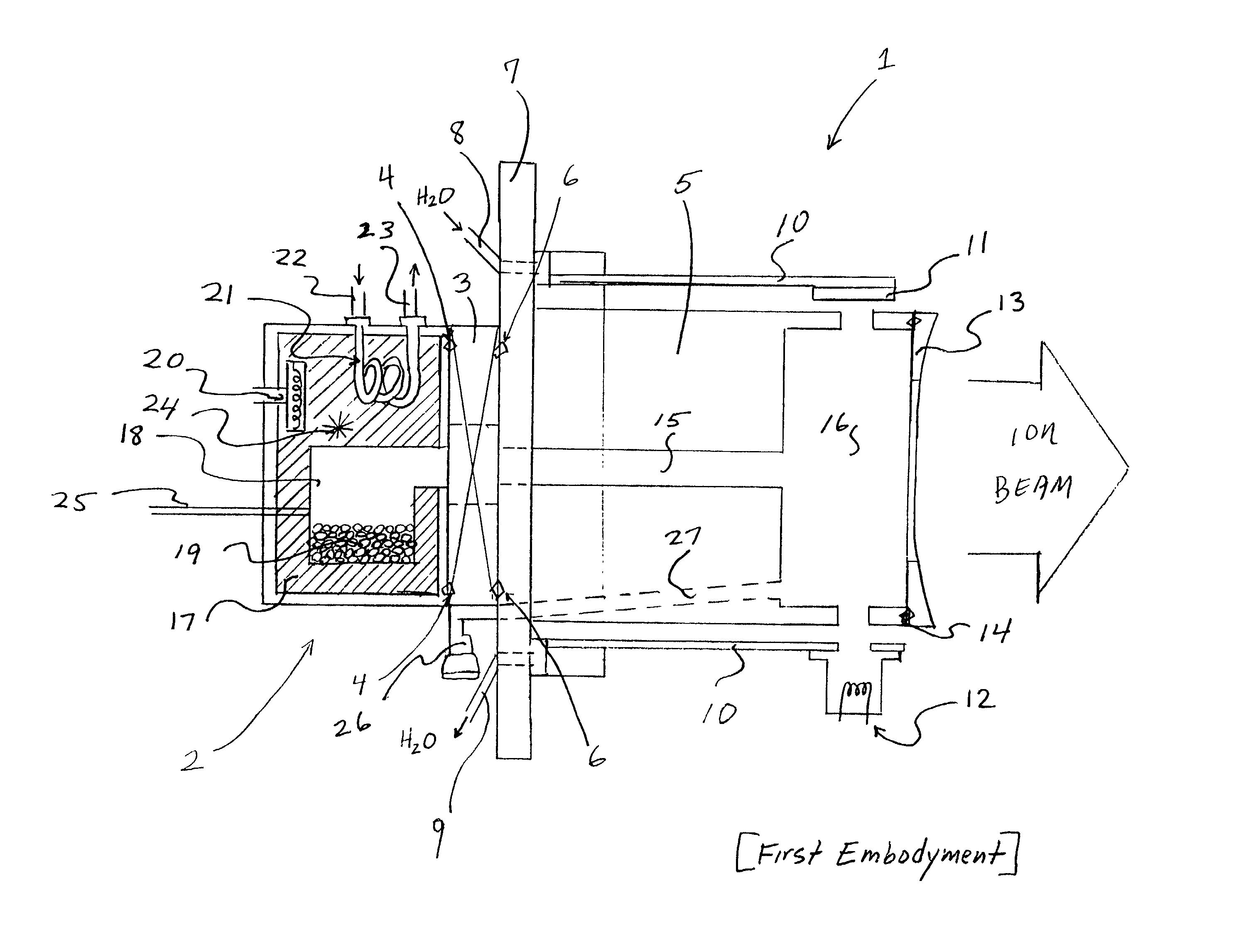
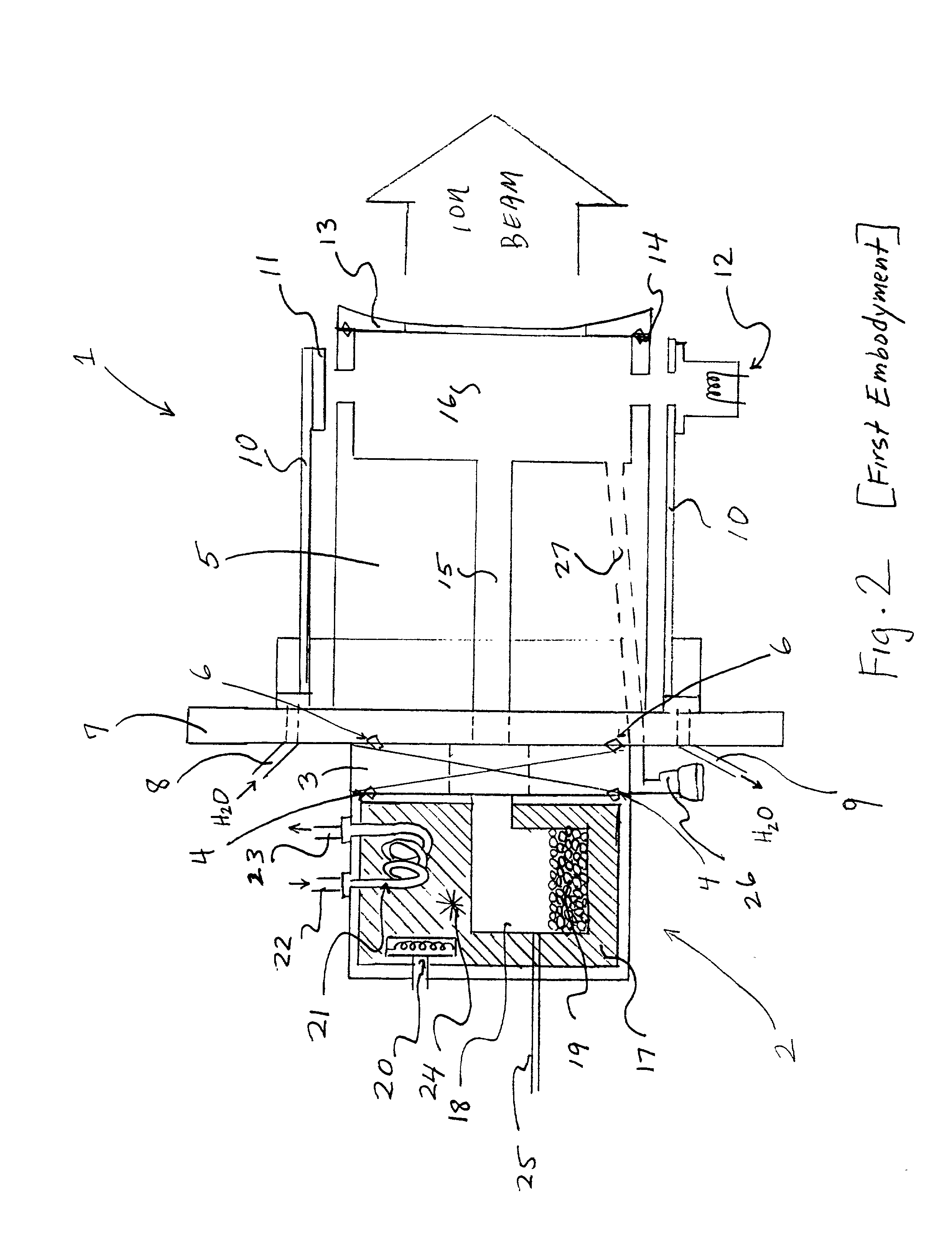
[0045] We refer now to the attached FIG. 2 through FIG. 7. FIG. 2 shows in schematic the first embodyment of the ion source 1. The vaporizer 2 is attached to the vaporizer valve 3 through a annular metal gasket 4. The vaporizer valve 3 is likewise attached to the ionization chamber 5 by a second annular metal gasket 6. This ensures good thermal conduction between the vaporizer, vaporizer valve, and ionization chamber 5 through intimate contact via thermally conductive elements. A mounting flange 7 attached to the ionization chamber 7 allows mounting of the ion source 1 to the vacuum housing of an ion implanter, and contains electrical feedthroughs (not shown) to power the ion source, and water-cooling feedthroughs 8, 9 to cool the ion source. In the preferred embodyment of the invention, water feedthroughs 8, 9 circulate water through the source shield 10 to cool the source shield 10 and cool the attached components, the beam dump 11 and electron gun 12. The exit aperture 13 is moun...


PUM


Abstract

An ion source for ion implantation system and a method of ion implantation employs a controlled broad, directional electron beam to ionize process gas or vapor, such as decaborane, within an ionization volume by primary electron impact, in CMOS manufacturing and the like. Isolation of the electron gun for producing the energetic electron beam and of the beam dump to which the energetic beam is directed, as well as use of the thermally conductive members for cooling the ionization chamber and the vaporizer, enable use with large molecular species such as decaborane, and other materials which are unstable with temperature. Electron optics systems, facilitate focusing of electrons from an emitting surface to effectively ionize a desired volume of the gas or vapor that is located adjacent the extraction aperture. The components enable retrofit into ion implanters that have used other types of ion sources. Demountable vaporizers, and numerous other important features, realize economies in construction and operation. Achievement of production-worthy operation in respect of very shallow implants is realized.

Description

[0001] We present the design and operation of an ion source for use in the ion implantation of semiconductors, and for the modification of the surfaces of materials. The ion source can be retrofitted into the existing fleet of ion implanters currently used in the manufacture of semiconductor devices, particularly those used in Complementary Metal-Oxide Semiconductor (CMOS) manufacturing. The ion source is specifically designed to accomodate the use of new solid feed materials such as decaborane (B.sub.10H.sub.14) and Trimethyl Indium (TMI), which vaporize at sufficiently low temperatures that currently available ion implant ion sources cannot use them. Indeed, the currently available ion sources result in dissociation of decaborane when that material is introduced into them. The ion source has an integral low-temperature vaporizer, and a means of introducing the vaporized feed material into an ionization chamber which is also temperature controlled by the vaporizer. The feed materia...

Claims


Application Information

Patent Timeline
IPC IPC(8): H01J37/08H01J37/317H01L21/265H01L21/425
CPCH01J37/08H01J37/3171H01L21/425H01L21/26513H01J2237/31701H01L21/2658
Inventor HORSKY, THOMAS N.
Owner SEMEQUIP
Why Eureka
Try Eureka