Methods for preparing polyvinylidene fluoride composites

a polyvinylidene fluoride and composite technology, applied in the direction of conductors, nanoinformatics, non-metal conductors, etc., can solve the problems of insufficient mechanical strength, high weight load, poor corrosion resistance of metal fiber and powder enhanced plastics, etc., to improve electrical conductivity, improve the intermixing effect of pvdf, and reduce bulk resistance

Inactive Publication Date: 2003-06-19
HYPERION CATALYSIS INT
View PDF0 Cites 25 Cited by
  • Summary
  • Abstract
  • Description
  • Claims
  • Application Information

AI Technical Summary

Benefits of technology

[0053] PVDF composites containing carbon nanotubes with different grades, sizes, morphologies, or types have different bulk resistivity at a given fibrinl loading. For example, it has been found that combed candy ("CC") nanotubes provide lower bulk resistivity than bird nest ("BN") nanotubes in PVDF composites at low nanotube loading. Without wishing to be bound by any theory, it is believed that CC nanotubes, which are aggregated in parallel bundles, are easier to disperse in the polymer than BN nanotubes, resulting in a more even distribution of fibrils in the composite and hence, lower bulk resistivity.
[0054] The conductivity levels obtained using PVDF composites formed from PVDF polymer or copolymers and carbon nanotubes make it possible to use conductive plastic, with all its property and fabrication advantages, in place of metals or pure graphite in a number of applications.
[0064] PVDF composites prepared using the solvent solution method have significantly lower bulk resistivity and thus were better electrical conductors, than PVDF composites made using traditional melt compounding methods. Without wishing to be bound by any theory, it is believed that the solvent solution method allows for better intermixing of the PVDF with the carbon nanotubes in the PVDF composites, thus resulting in lower bulk resistivity.
[0065] It has also been found that at low nanotube loadings, using sonicators or ultrasonic sonifiers resulted in PVDF composites having lower bulk resistivities than PVDF composites made using mechanical mixing means such as Waring blenders. Without wishing to be bound by any theory, it is also believed that sonicators or ultrasonic sonifiers are able to better disperse low levels of nanotubes in the polymer than mechanical mixing means, resulting in better distribution of nanotubes within the composite and hence, better conductivity.

Problems solved by technology

Metallic fiber and powder enhanced plastics have poor corrosion resistance and insufficient mechanical strength.
Further, their density makes high weight loadings necessary.
Thus, their use is frequently impractical.
When polyacrylonitrile ("PAN") or pitch-based carbon fiber is added to create conductive polymers, the high filler content necessary to achieve conductivity results in the deterioration of the characteristics specific to the original resin.
If a final product with a complicated shape is formed by injection molding, uneven filler distribution and fiber orientation tends to occur due to the relatively large size of the fibers, which results in non-uniform electrical conductivity.
The use of carbon black, however, also has a number of significant drawbacks.
These relatively high loadings lead to degradation in the mechanical properties of the polymers.
Specifically, low temperature impact resistance (i.e., a measure of toughness) is often compromised, especially in thermoplastics.
Barrier properties also suffer.
This is particularly undesirable in many electronic applications.
This adversely affects the surface finish.
Even in the absence of outgassing, high loadings of carbon black may render the surface of conductive plastic parts unsuitable for automotive use.
Taken as a whole, these drawbacks limit carbon black filled conductive polymers to the low end of the conductivity spectrum.
What ultimately limits the amount of carbon black that can be put into plastic is the ability to form the part for which the plastic is desired for.

Method used


Image

  • Methods for preparing polyvinylidene fluoride composites
  • Methods for preparing polyvinylidene fluoride composites
  • Methods for preparing polyvinylidene fluoride composites

Examples


example i

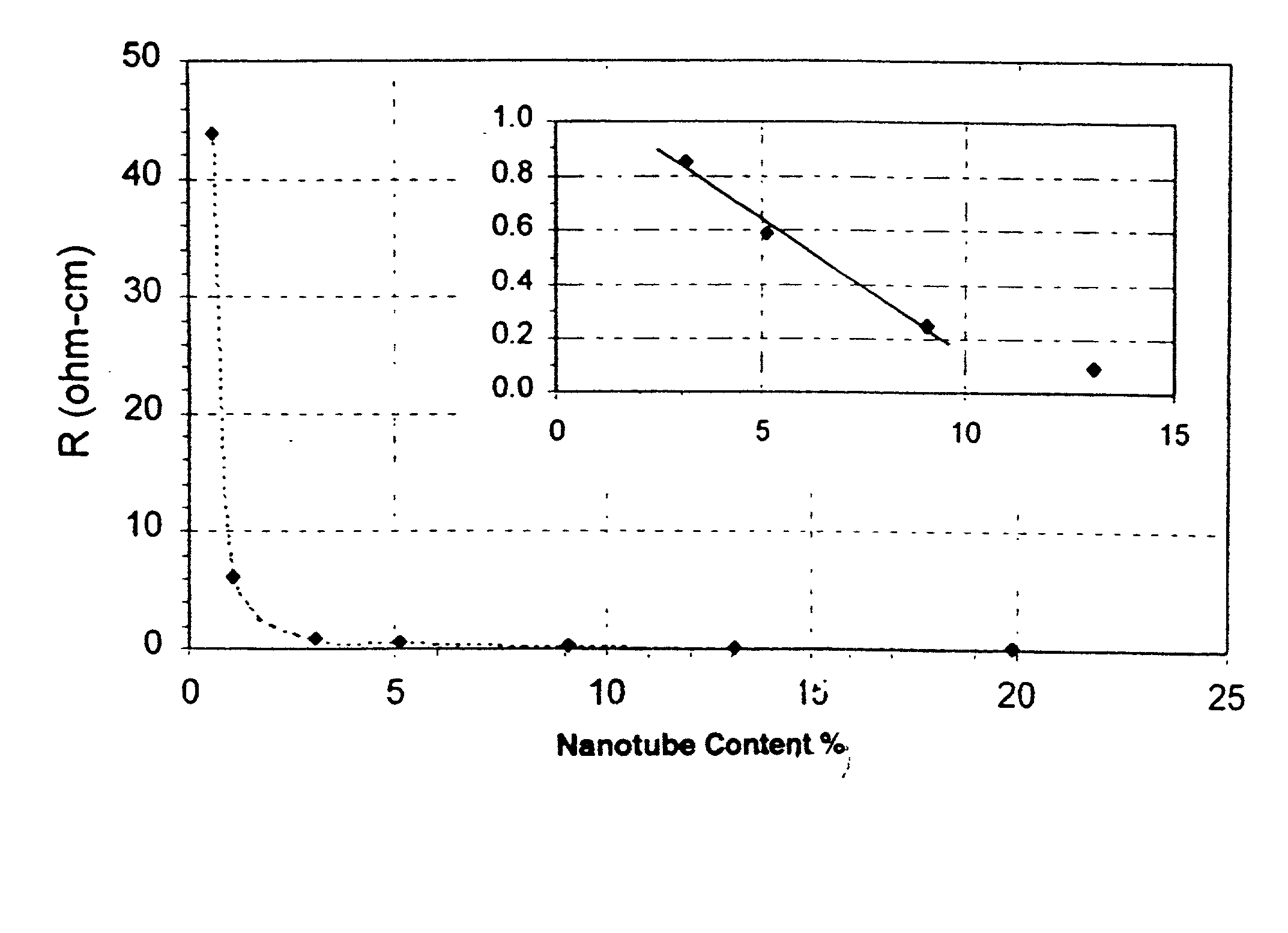
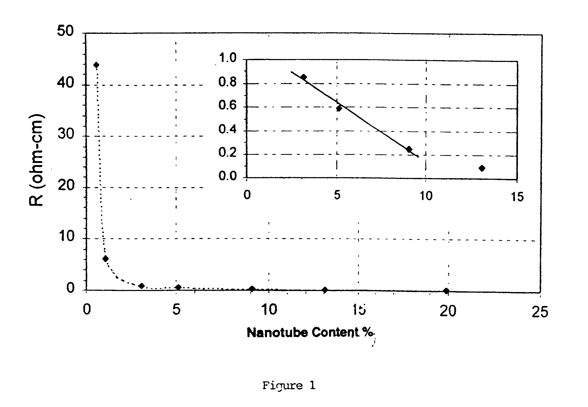
[0068] A PVDF polymer, Kynar 761, was obtained from Elf Atochem and dissolved in acetone. Hyperion CC carbon nanotubes were added and dispersed into the polymer solution for two to five minutes using a high shear blender (i.e., Waring blender). Water was added to the dispersion to precipitate out the polymer with the nanotubes. The material was filtered and the filtrate was dried in a vacuum oven at 100.degree. C. to remove acetone and water, leaving behind the dry nanotube / PVDF composite. Multiple sheets of the composite with thickness of 0.003-0.01 inches were made using a compression molder. Bulk resistivity of the thin sheet samples was measured using a four probe method. Tensile strength was also measured. Multiple batches with different amounts of carbon nanotubes were tested. The results are reported in Table 1 below:

1TABLE 1 Nano- Nano- Thick- Tensile tubes PVDF tubes ness Strength Resistivity Batch # (g) (g) (%) (inch) (psi) (Ohm-cm) 1 .02 10 0.20 -- -- 300,000 2 .09 10 0.8...

example ii

[0070] Using the procedure of Example I and Kynar 761 PVDF, a comparison was made of the resistivity of composites prepared with Hyperion CC nanotubes and with Hyperion BN nanotubes, respectively. The results are reported in Table 2 below:

2 TABLE 2 CC Nanotubes BN Nanotubes Tensile Tensile Nanotubes Resistivity Strength Resistivity Strength Batch # (%) (ohm-cm) (psi) (ohm-cm) (psi) 1 1 19.17 8145 12987 --2 5 0.4242 6739 4.1081 6663 3 7 0.2825 6770 1.6136 7227 4 11 0.1290 7144 0.4664 7201

[0071] The results of Example II confirm that at low nanotube loadings, PVDF / CC nanotube composites have significantly lower bulk resistivity than PVDF / BN nanotube composites.

example iii

[0072] Example I was repeated, except that an ultrasound sonicator or a homogenizer was used instead of a Waring blender to disperse the nanotubes in the polymer solution. The results are reported below in Table 3:

3TABLE 3 Nanotubes Thickness Dispersion Resistivity Batch # (%) (inch) Method (ohm-cm) 1 1.05 0.0058 Sonicator 11.7122 2 3.03 0.0080 Sonicator 0.6144 3 13.04 0.0130 Sonicator 0.0924 0.0110 Sonicator 0.0959 4 13.04 0.0100 Homogenizer 0.1168 0.0110 Homogenizer 0.1028 5 20.00 0.0090 Homogenizer 0.0381 0.0090 Homogenizer 0.0509

[0073] These results revealed that PVDF composites with low carbon nanotube loadings made with a sonicator generally had lower bulk resistivities than composites which were made with a Waring blender. PVDF composites made with a homogenizer had similar bulk resistivity values to those made with a Waring blender.


PUM

PropertyMeasurementUnit
diameteraaaaaaaaaa
diameteraaaaaaaaaa
diameteraaaaaaaaaa

Abstract

An electrically conductive composite comprising a polyvinylidene fluoride polymer or copolymer and carbon nanotubes is provided. Preferably, carbon nanotubes may be present in the range of about 0.5-20% by weight of the composite. The composites are prepared by mixing or dispersing carbon nanotubes in polymer emulsion using an energy source such as a Waring blender. The liquid in the mixture is then evaporated to obtain the composite comprising the polymer and the nanotubes.

Description

[0001] This application is a continuation in part of U.S. Ser. No. 09 / 903,189, filed Jul. 11, 2001.[0002] The invention relates generally to electrically conductive polyvinylidene fluoride composites containing carbon nanotubes, and the methods for preparing them.[0003] Polyvinylidene Fluoride Plastics are synthetic polymers which have a wide range of properties that make them useful for a variety of applications ranging from packaging and building / construction to transportation; consumer and institutional products; furniture and furnishings; adhesives, inks and coatings and others. In general, plastics are valued for their toughness, durability, ease of fabrication into complex shapes and their electrical insulation qualities.[0004] One such widely used plastic is polyvinylidene fluoride (--H.sub.2C.dbd.CF.sub.2--), ("PVDF"), which is the homopolymer of 1,1-difluoroethylene, and is available in molecular weights between 60,000 and 534,000. This structure, which contains alternating...

Claims


Application Information

Patent Timeline
Patent Type & Authority Applications(United States)
IPC IPC(8): C08J3/21C08K7/24H01B1/24
CPCB82Y10/00B82Y30/00C08J3/212C08J2327/16Y10S977/788H01B1/24C08K7/24Y10S977/742C08L27/16
Inventor NIU, CHUNMINGNGAW, LEIN
Owner HYPERION CATALYSIS INT
Why Eureka
Try Eureka