Solid material for magnet

a solid material and magnet technology, applied in the direction of magnetic materials, magnetic bodies, inductance/transformer/magnet manufacturing, etc., can solve the problems of difficult to solidify the same through self-sintering, the type of bonded magnet cannot be employed, and the difficulty of industrially applying such a compacting pressur

Inactive Publication Date: 2004-08-05
ASAHI KASEI KK
View PDF7 Cites 24 Cited by
  • Summary
  • Abstract
  • Description
  • Claims
  • Application Information

AI Technical Summary

Benefits of technology

[0022] A second object of the present invention is to provide a solid material for a magnet, characterized in that said solid material includes an R--Fe--N--H system magnetic material having a rhombohedral or hexagonal crystal structure in an amount of 80 to 97% by volume; has a low density of 6.15 to 7.45 g / cm.sup.3; and is excellent in magnetic properties and stability in spite of its light-weight, and to provide a method of producing the same. According to the present invention, the solid material for a magnet, which also includes a magnet as magnetized by magnetization or the like, is provided.
[0025] Besides, in order to derive a high-density R--Fe--N--H system solid material for a magnet having a rhombohedral or hexagonal crystal structure with good reproducibility, the present inventors have been devoted to investigating a composition of powders and a method of producing the solid material. Consequently, they have had information that a solid material for a magnet, which comprises an R--Fe--N--H system magnetic material, has a density of larger than 7.45 g / cm.sup.3 and (BH).sub.max of 200 kJ / m.sup.3 or more, and is solidified by metallic bonds can be easily derived by the steps of: forming powders of a magnetic material including hydrogen and nitrogen in a magnetic field into a powder compact; and thereafter subjecting said powder compact to shock-compression by means of underwater shock-waves having a specific shock-waves pressure while preventing decomposition and denitrification, whereby the present invention has been accomplished.
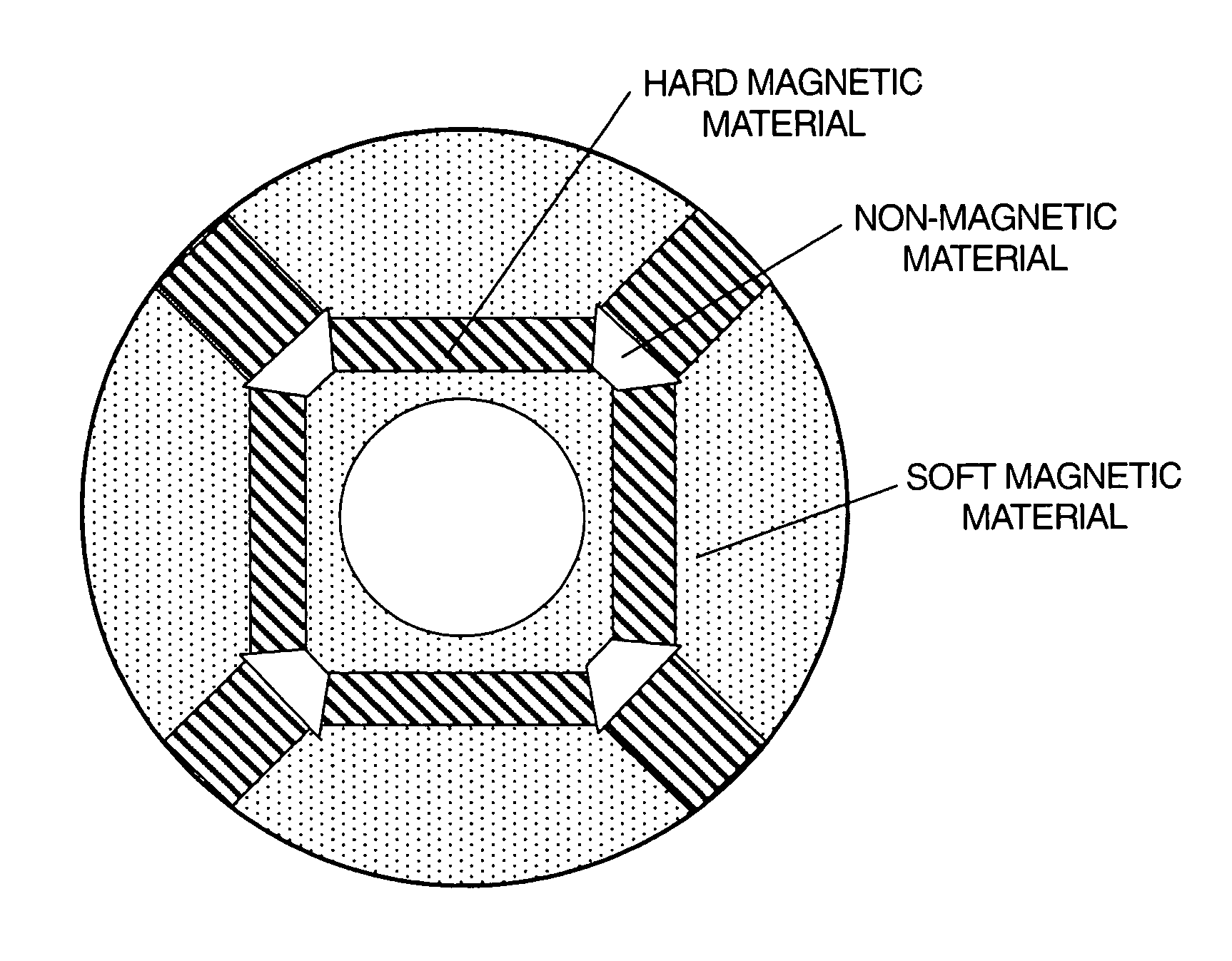
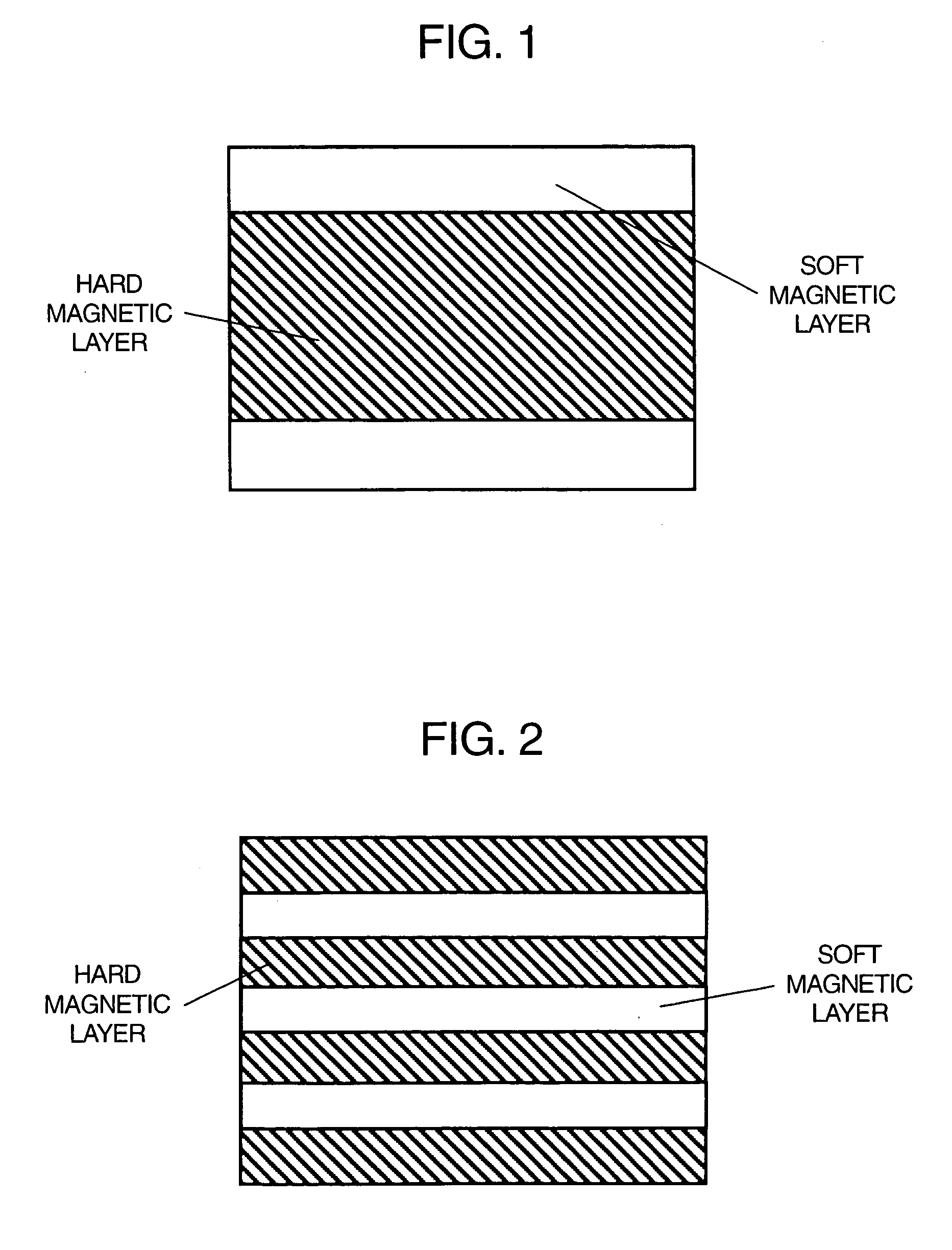
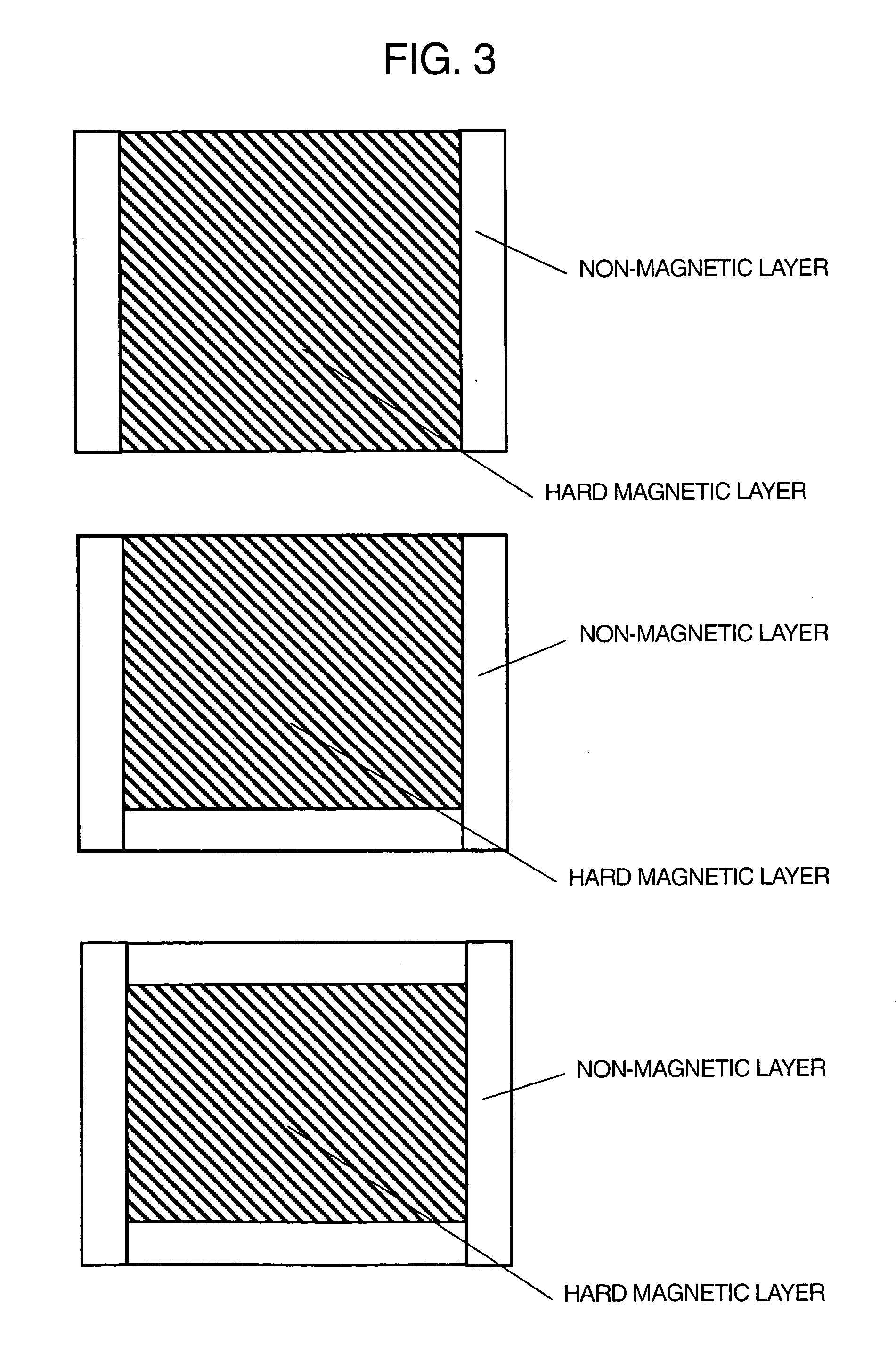
[0026] Furthermore, the present inventors have also found that when the above underwater shock waves were used, an R--Fe--N--H system magnetic material and a hard-magnetic and / or soft-magnetic powders or solid material, or a non-magnetic powders or solid material can be easily integrated, whereby the present invention has been accomplished.

Problems solved by technology

However, since it is easily decomposed into an .alpha.-Fe decomposed phase and a rare-earth nitride phase at a temperature of about 600.degree. C. or more at normal pressures, it is very difficult to solidify the same by means of self-sintering so as to prepare a solid material for a magnet according to ordinary industrial processes.
That is, when a brushless motor or the like as a power source which is used in a high-temperature environment of 150.degree. C. or more by request for a recent high loading is manufactured, there has existed the problem that this type of bonded magnet can not be employed.
Besides, when a compression-molded bonded-magnet including a resin as a binder is manufactured, there has existed the problems that a compacting pressure of 1 GPa or more is necessary in order to enhance the packing fraction to offer technical advantages, but it is difficult to industrially apply such a compacting pressure; considering the useful life of a mold, the mixture ratio of a magnetic material is forced to be set to less than 80% in volume fraction in most cases; and thus the compression-molded bonded-magnet can not satisfactorily bring out excellent basic magnetic properties of the R--Fe--N--H system magnetic material.
However, this bonded magnet does not satisfactorily bring out high basic magnetic properties of the R--Fe--N--H system magnetic material as compared with those of a conventional Sm--Co system or Nd--Fe--B system sintered magnet or the like.
However, this method had the disadvantage that the pressure for shock compression had to be limited within a certain range in order to inhibit a residual temperature after the shock compression to the decomposition temperature of Th.sub.2Zn.sub.17 type rare-earth / iron / nitrogen system magnetic material, or to a temperature less than the decomposition temperature.
This is because when conventional shock waves are used, in spite of a short duration of the shock-waves as such, the temperature of the magnetic material is high and is maintained over a long period of time, and consequently, the magnetic material may be decomposed.
Furthermore, according to such a method, the density of the resultant material was limited to 7.28 g / cm.sup.3 even at the maximum.
However, even in the magnet provided according to this method, the maximum value of the density is 7.43 g / cm3 and the maximum value of the coercive force was 0.62 MA / m, which were not satisfactory.
Furthermore, since some applications have enough room for magnetic properties, even if weight saving is achievable by downsizing the magnet, considering a process yield, it could not be necessarily said to be advantageous in cost.
Various bonded magnets are poor in thermal stability as described above.
When the volume fraction is less than 80% by volume, continuous bindings among magnetic particles are not satisfactory, whereby a solid material for a magnet is not formed.
Conversely, when the average particle size is larger than 100 .mu.m, the coercive force is decreased so as to come to be poor in practicability.
One of large features of an R--Fe--N--H system magnetic material is the point that oxidation resistance is relatively high, and rust is difficult to start.
However, since the surface of the sintered magnet is easily oxidized even in the atmosphere at normal room temperature, the sintered magnet has to be surface-treated by nickel-plating, by coating with an epoxy-resin, or the like for the purpose of rust removal.
Furthermore, since the R--Fe--N--H system solid material for a magnet is in the form of powders in many cases, if there are many passthroughs for oxygen which are continuous pores, such as voids, the surfaces of the powders are oxidized and deteriorated, which gives rise to the decrease of the coercive force.
However, when a solid material for a magnet is composed of a unique R--Fe--N--H system magnetic material, and the remainder is the atmosphere, if the density of said solid material is 7.45 g / cm.sup.3 or less, even if a magnet having any form and volume is formed, the magnet includes a lot of voids, which often gives rise to a crack and / or a break, and the coercive force may be frequently decreased as mentioned above.
Consequently, a high-performance solid material for a magnet can not be formed according to a conventional shock-waves compression method.
When powders of an R--Fe--N--H system magnetic material and a soft magnetic bulk-material or powder are simultaneously loaded without mixing both materials, and are subjected to shock-wave compression, since the solidification of the R--Fe--N--H system magnetic material and the integration of the same with the soft magnetic material can be simultaneously carried out, and none of cutting-out, welding, or bonding with an adhesive agent and the like is necessary for the purpose of the integration of the materials at a post-process, and thus a merit in cost is large, which is a distinguishing feature of the present invention.
Then, the solid material for a magnet is provided with a great shock, whereby even the compactly solidified R--Fe--N--H system solid material for a magnet may be cracked and / or chipped.
However, in a severe environment at an elevated-temperature and high-humidity, such a magnetic-material / organic-matter composite solid material for a magnet may be not to be used.
When the operating point of the magnet is on the side of a magnetic field higher than the critical point, the magnet is rapidly demagnetized, whereby the performance of the magnet can not be effectively achieved, and thus the operating point should be on the side of a magnetic field lower than the critical point.
However, if at least the condition defined by the expression (2) is not satisfied, remarkable demagnetization induced by using the magnet can not be avoided.
In addition to the above, as the large cause of lowering thermal stability, the fact that magnetic powders are not sufficiently bonded to one another by metallic bonds for solidification can be enumerated.
Poor thermal-stability can be said to be a problem caused thereby.
However, in the case of a magnetic material / gas composite solid material for a magnet, an excessive shock-wave pressure easily forms a solid material for a magnet having a density of larger than 7.45 g / cm.sup.3.
In the application wherein the maximum working temperature (T.sub.max) is 100.degree. C. or more, since a conventional R--Fe--N--H system bonded magnet includes a resin component and no magnetic powders are bonded to one another by metallic bonds and solidified, the magnet was poor in thermal stability, and difficult to be used.
However, when an R--Fe--N--H system magnetic material used as a raw material for a solid material for a magnet originally includes such a material as has a peak near 44.degree., such as a Fe-soft magnetic material, the criterion mentioned above can not be applied thereto.

Method used


Image

  • Solid material for magnet
  • Solid material for magnet
  • Solid material for magnet

Examples


example 2

[0227] Powders of Sm and Fe metals in a predetermined amount (at a weight ratio of 16.85:83.15) were subjected to a mechanically-alloying treatment by means of a vibration ball-mill for a period of 180 ks, and thereafter heat-treated at a temperature of 600.degree. C. in vacuum for a period of 7.2 ks. These powders included about 30% by volume of a Fe soft-magnetic material. The powders were subjected to nitrogenation and hydrogenation at a temperature of 380.degree. C. in an ammonia-hydrogen mixed gas flow-current having an NH.sub.3-partial pressure of 0.35 atm and a H.sub.2-partial pressure of 0.65 atm for a period of 1.2 ks, and subsequently heat-treated at the same temperature in hydrogen for a period of 300 seconds. Using these powders, a solid material for a magnet having a composition of Sm.sub.6.1Fe.sub.81.6N.sub.9.2H.sub.3.1 was produced in a similar manner to the one in Example 1, except that the pressure of shock-waves was set to 18 GPa.

[0228] This solid material for a ma...

example 3

[0230] R--Fe--N--H system powders having an average particle size of 2 .mu.m which had been derived in Example 1, and Sm--Co system powders having an average particle size of 25 .mu.m and a composition of Sm.sub.11.5Co.sub.57.6Fe.sub.24.8Cu.sub.4.4Zr.sub.1.7 were charged into an agate mortar so that a volume ratio of 50:50 could be derived, and were wet-blended in cyclohexane.

[0231] Using these blended powders, an R--Fe--N--H system solid material for a magnet was prepared in a similar manner to the one in Example 1, except that the pressure of shock waves was set to 14 GPa. This solid material for a magnet was magnetized in a pulsed magnetic field of 4.0 MA / m, and the magnetic properties were determined. Resultantly, a residual magnetic flux density (B.sub.r)=1.10 T, a coercive force (H.sub.cJ)=0.83 MA / m, (BH).sub.max=209 kJ / m.sup.3 were derived.

example 4

[0232] According to a photolysis method using publicly known diethyl zinc, Sm--Fe--Co--N--H magnetic powders having an average particle size of about 1 .mu.m, the surfaces of which were coated with a Zn-metal were prepared. Using these powders, a solid material for a magnet having a composition of Sm.sub.8.4Fe.sub.64.3Co.sub.7.1N.sub.12.6H.sub.3.4Zn.sub.4-.2 was produced in a similar manner to the one in Example 1, except that the pressure of shock waves was set to 16 GPa.

[0233] This solid material for a magnet was magnetized in a pulsed magnetic field of 4.0 MA / m, and the magnetic properties were determined. Resultantly, a residual magnetic flux density (B.sub.r)=1.27 T, a coercive force (H.sub.cJ)=0.76 MA / m, (BH).sub.max=257 kJ / m.sup.3, and a density of 7.71 g / cm.sup.3 were derived. Furthermore, it was analyzed according to an X-ray diffraction method. Resultantly, it was confirmed that the solidified solid material for a magnet has a crystal structure of Th.sub.2Zn.sub.17-type rh...


PUM

PropertyMeasurementUnit
densityaaaaaaaaaa
densityaaaaaaaaaa
densityaaaaaaaaaa

Abstract

A solid material for a magnet, comprising a rare-earth / iron / nitrogen / hydrogen system magnetic material.

Description

[0001] The present invention relates to a rare-earth / iron / nitrogen / hydroge-n system solid material for a magnet, which has a high density and superior magnetic properties and is excellent in thermal stability and oxidation resistance. The present invention also relates to a rare-earth / iron / nitrogen / hydrogen system solid material for a magnet, which in spite of lightness in weight, has superior magnetic properties and has excellent thermal stability.[0002] The present invention relates to a device and a part, wherein a magnet comprising said solid material is utilized.[0003] The present invention also relates to a method of producing a solid material for a magnet, comprising the step of subjecting magnetic material powders to shock-compression with decomposition and denitrification prevented, so as to provide a high-performance permanent magnet with a high density.[0004] The term "a solid material" herein referred to indicates a bulk material. Furthermore, the term "a solid material ...

Claims


Application Information

Patent Timeline
Patent Type & Authority Applications(United States)
IPC IPC(8): B01J3/08B22F3/08C22C38/00H01F1/059H01F41/02
CPCB01J3/08B22F3/08H01F41/0273H01F1/0596C22C38/005C22C38/002C22C38/001B22F2998/10B22F2999/00B22F2202/05B22F3/087B22F2201/05H01F1/053
Inventor KAKIMOTO, ETSUJIDOHKE, KIYOTAKASHIBASAKI, ICHIROIMAOKA, NOBUYOSHICHIBA, AKIRA
Owner ASAHI KASEI KK
Why Eureka
Try Eureka