Combined activated sludge-biofilm sequencing batch reactor and process

a technology of activated sludge and batch reactor, which is applied in the direction of filtration separation, multi-stage water/sewage treatment, separation process, etc., can solve the problems of large volume bioreactor tank, rate-limiting step that requires long operating sludge ages, and only able to meet non-stringent discharge standards, etc., to achieve similar oxygen transfer efficiency, promote removal, increase

Inactive Publication Date: 2004-10-21
KINGSFORD ENVIRONMENTAL H K
View PDF11 Cites 84 Cited by
  • Summary
  • Abstract
  • Description
  • Claims
  • Application Information

AI Technical Summary

Benefits of technology

0057] For aerobic treatment, the carriers also allow less costly coarse bubble diffusers and jet aerators to be used with similar oxygen transfer efficiency to that of the membrane fine-bubble diffusers. The ability of the system to simultaneously have both aerobic and anoxic conditions present at the sa...

Problems solved by technology

While very basic technologies such as land & grass filtration, septic tanks/soak-away pit and stabilization ponds are still widely and appropriately used in many developing countries, these technologies are only able to meet non-stringent discharge standards.
Growth of slow growing and sensitive bacteria such as nitrifiers and those required to break down complex refractory organics is a rate-limiting step that requires long operating sludge ages to achieve the desired effluent quality.
The resultant low food:microorganism ratio (F/M) results in large volume bioreactor tanks.
The secondary clarifiers also have large volume requirements, particularly if the operating sludge age is long, which typically results in poorly settling sludge.
Handling of the excess sludge also requires substantial capital investment and higher operating costs.
In highly populated regions, land limitations restrict the feasibility of using conventional activated sludge with clarifier systems.
However, the SBR sy...

Method used


Image

  • Combined activated sludge-biofilm sequencing batch reactor and process
  • Combined activated sludge-biofilm sequencing batch reactor and process
  • Combined activated sludge-biofilm sequencing batch reactor and process

Examples


case 1 two

[0122] Case 1 Two-Stage and Two-Sludge Aerobic-Aerobic Process for Organics & Suspended Solids Removal Only

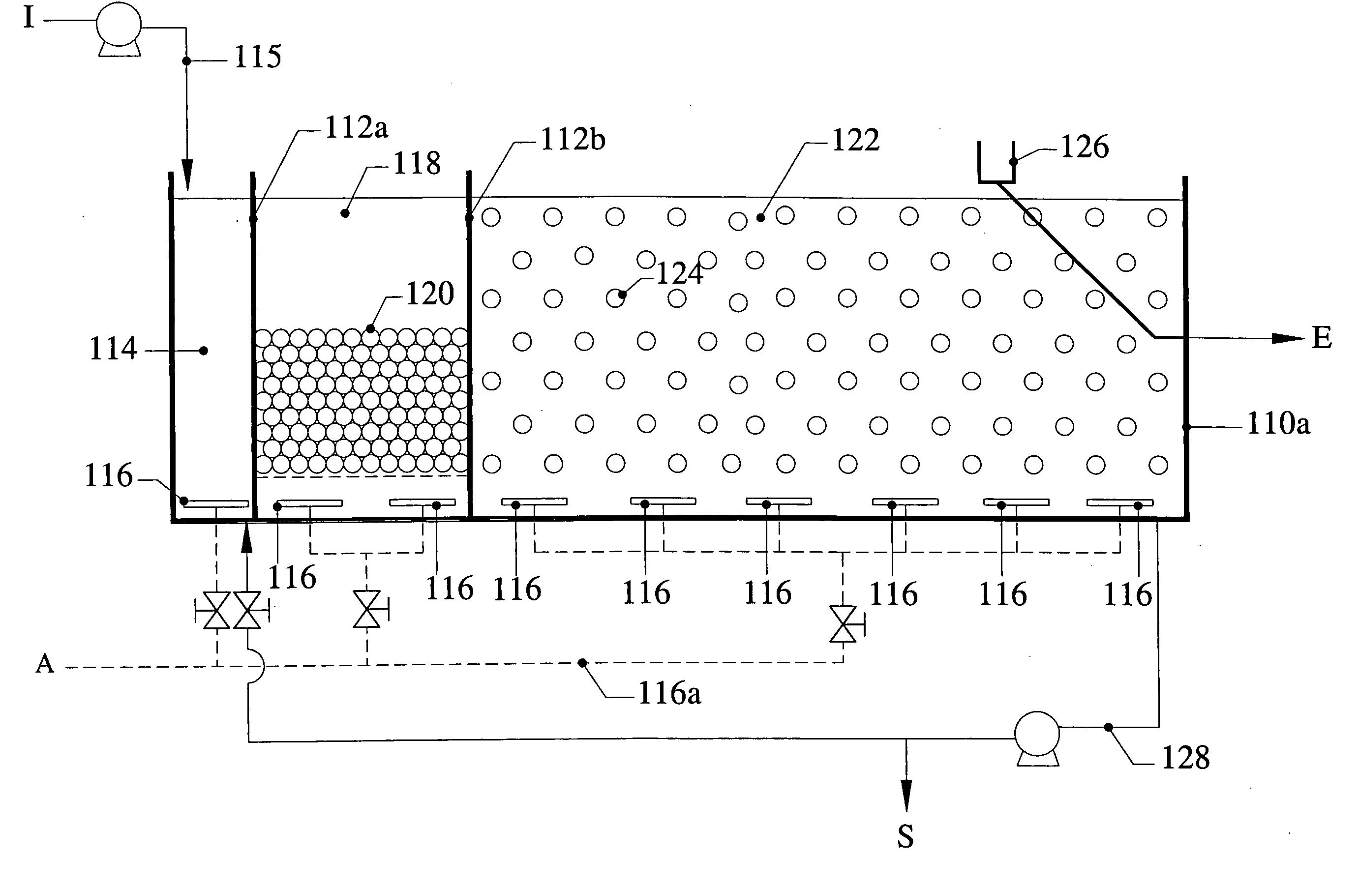
[0123] One of the possible two-stage two-sludge SBR3 system configuration is illustrated in FIG. 1. The cycle sequence of the SBR3 process of case 1 is illustrated in FIGS. 7A and 7B. The cycle starts from step 7A1, going through steps 7A2, 7B1, and 7B2, and goes back to step 7A1. In this process, the three tanks are used for:

[0124] (1) the first stage RC (performed in the second tank 118); and

[0125] (2) the second stage SC (performed in the third tank 122).

[0126] For the ease description of the bio-chemical processes, the following description contains reference only to the biochemical stage without further reference to the particular tanks as shown in FIG. 1, 7A or 7B. It is understood that these processes are performed in the respective tanks.

[0127] In this case, the bioselector of RC Stage is shown as part of the RC Stage. This configuration consists of an RC Stage with RC ...

case 2 two

[0133] Case 2 Two-Stage and Two-Sludge Anoxic / Aerobic-Anoxic / Aerobic Process for Organics-Suspended Solids-Nitrogen Removal Only

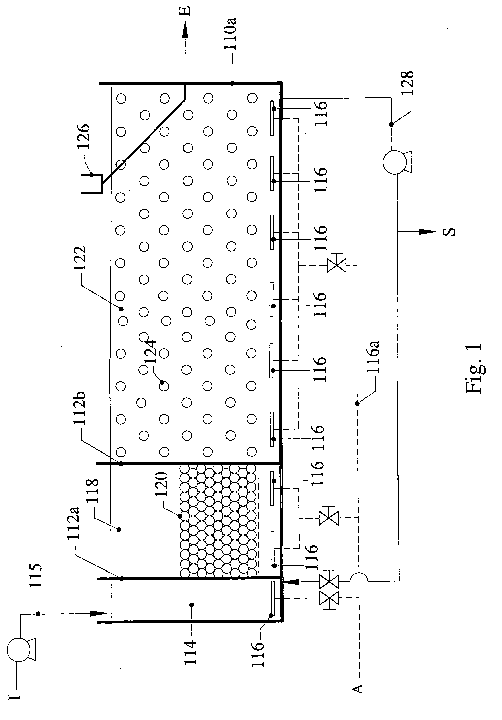
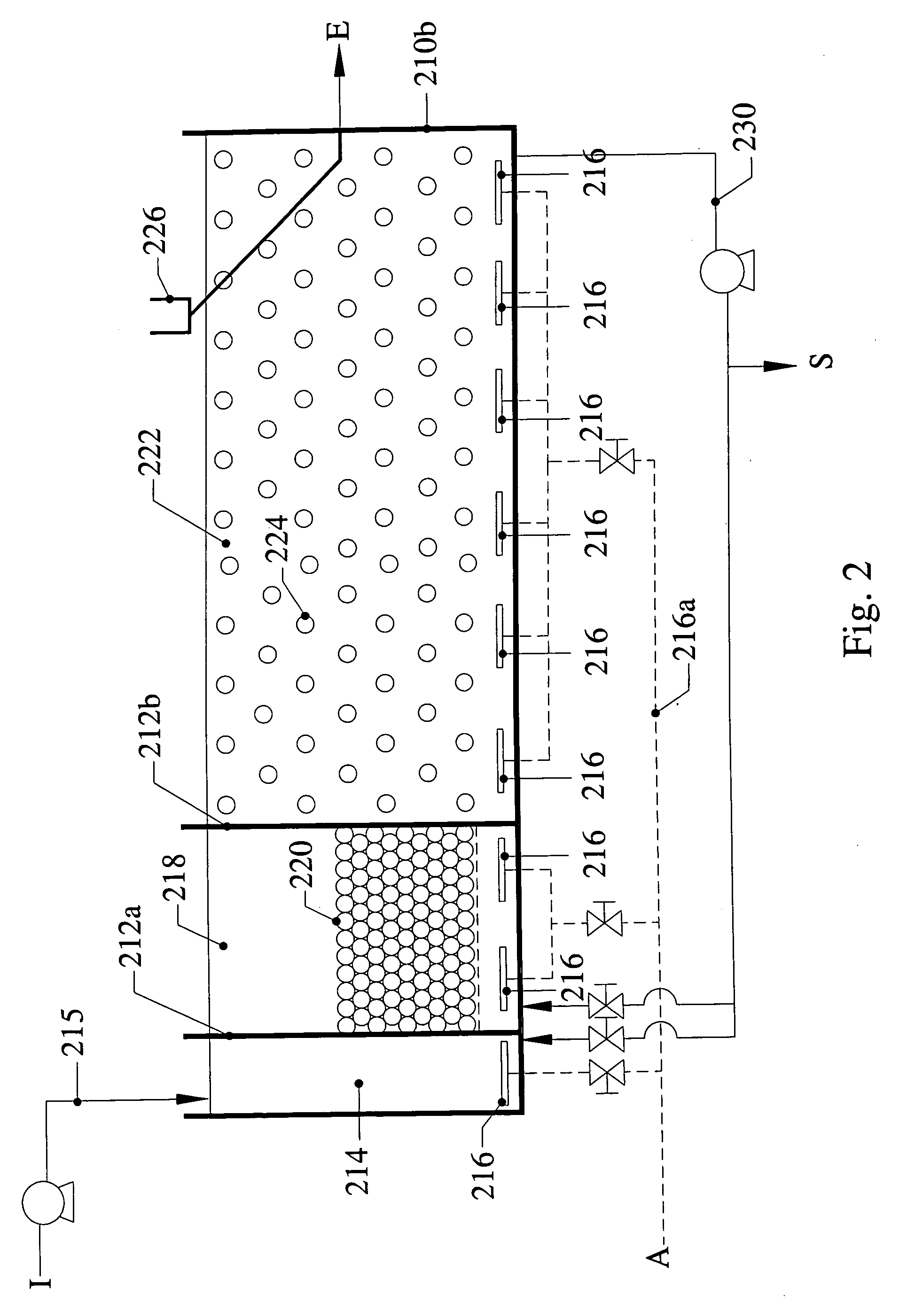
[0134] One of the possible two-stage two-sludge SBR3 system configurations is illustrated in FIG. 2. Note that an optional Bioselector (BS) is shown as part of the DN Stage. The cycle sequence of the SBR3 process of case 2 is illustrated in FIGS. 8A and 8B. The cycle starts from step 8A1, going through steps 8A2, 8B1, and 8B2, and goes back to step 8A1. In this process, the three tanks are used for:

[0135] (1) The first stage DN (performed in the second tank 218);

[0136] (2) The second stage N (performed in the third tank 222).

[0137] For the ease description of the biochemical processes, the following description contains reference only to the biochemical stage without further reference to the particular tanks as shown in FIG. 2, 8A and 8B. It is understood that these processes are performed in the respective tanks.

[0138] This configuration consists of a DN S...

case 2 experimental

[0144] Case 2 Experimental Data

[0145] Two fully automatic PLC controlled SBR pilot-scale reactors were built including an on-line wastewater sampling, monitoring and control system. The SBR3 included biofilm carriers with configuration as shown in FIG. 3 and the "conventional SBR" was identical to the SBR3 except that it had no biofilm carriers and was used as a control.

[0146] A Two-Stage Two-Sludge SBR3 was tested: one stage each for nitrification (N Stage) and denitrification (DN Stage), with DN Sludge on the mobile carriers that remain settled at the bottom of the tank when no external mixing is provided in the DN Stage (main role: denitrification) and the N Sludge consisting of the biofilm on the suspended carriers in N Stage (main role: nitrification). Activated sludge was also present, but not associated with any particular stage.

[0147] Configuration and Operation for Initial Phase of Testing

[0148] The initial configuration and operation of the SBR3 for nitrogen removal is sho...


PUM

PropertyMeasurementUnit
Fractionaaaaaaaaaa
Fractionaaaaaaaaaa
Fractionaaaaaaaaaa

Abstract

A new biofilm-activated sludge Sequencing Batch Reactor (SBR) treatment process for sewage or wastewater has successfully been developed as the third generation SBR (SBR3). This new SBR3 process utilizes a multi-stage and multi-sludge SBR configuration receiving either continuous or intermittent inflow of wastewater. Each stage has individually controlled continuous or alternating anaerobic/anoxic/aerobic operation, with or without mixing and recycling from the other stage(s). The configuration and operation is dependent upon the treatment objectives and effluent discharge requirements. In the preferred embodiment, carriers are used to facilitate control of operating conditions.

Description

[0001] Pursuant to 35 USC .sctn. 119(e), this application claims benefit of prior U.S. provisional application 60 / 393,043, filed Jun. 28, 2002.[0002] This invention relates to sewage and wastewater treatment and in particular to biological treatment of wastewater using a sequencing batch reactor configuration.BACKGROUND OF INVENTION[0003] While very basic technologies such as land & grass filtration, septic tanks / soak-away pit and stabilization ponds are still widely and appropriately used in many developing countries, these technologies are only able to meet non-stringent discharge standards. More advanced technologies must be used to meet increasingly more stringent effluent discharge requirements. These advanced technologies are based on the use of microbial activity under aerobic and / or anaerobic and / or anoxic treatment conditions to meet different and multiple treatment objectives. Treatment objectives range from the removal of simple organics (biological oxygen demand [BOD], c...

Claims


Application Information

Patent Timeline
IPC IPC(8): C02F3/00C02F3/06C02F3/12C02F3/30
CPCC02F3/06C02F3/085C02F3/1263C02F3/301C02F3/302C02F2003/001Y10S210/903Y10S210/906Y02W10/10
Inventor HO, KIN MANGREENFIELD, PAUL F.ECKENFELDER, W. WESLEY JR.
Owner KINGSFORD ENVIRONMENTAL H K
Why Eureka
Try Eureka