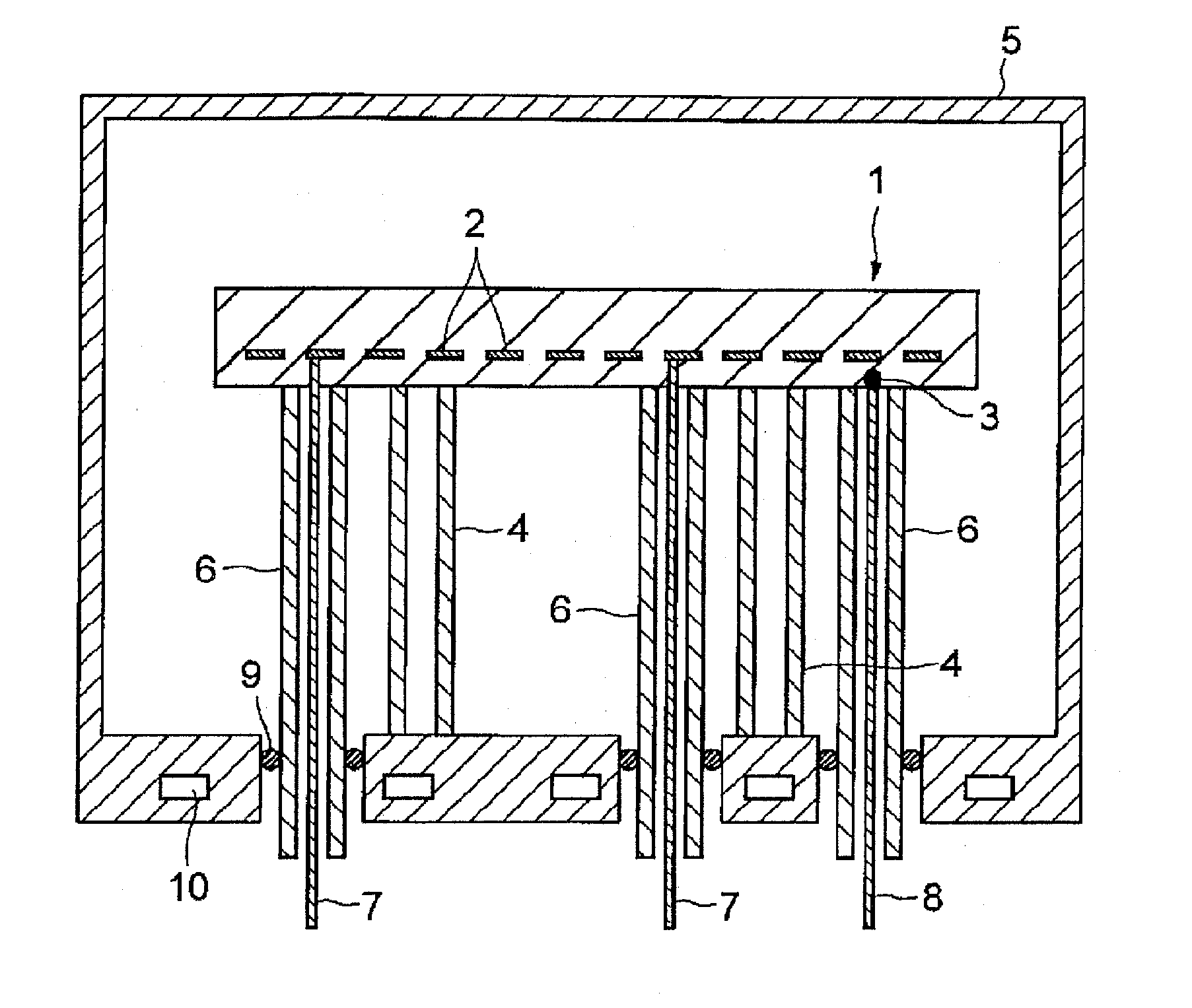
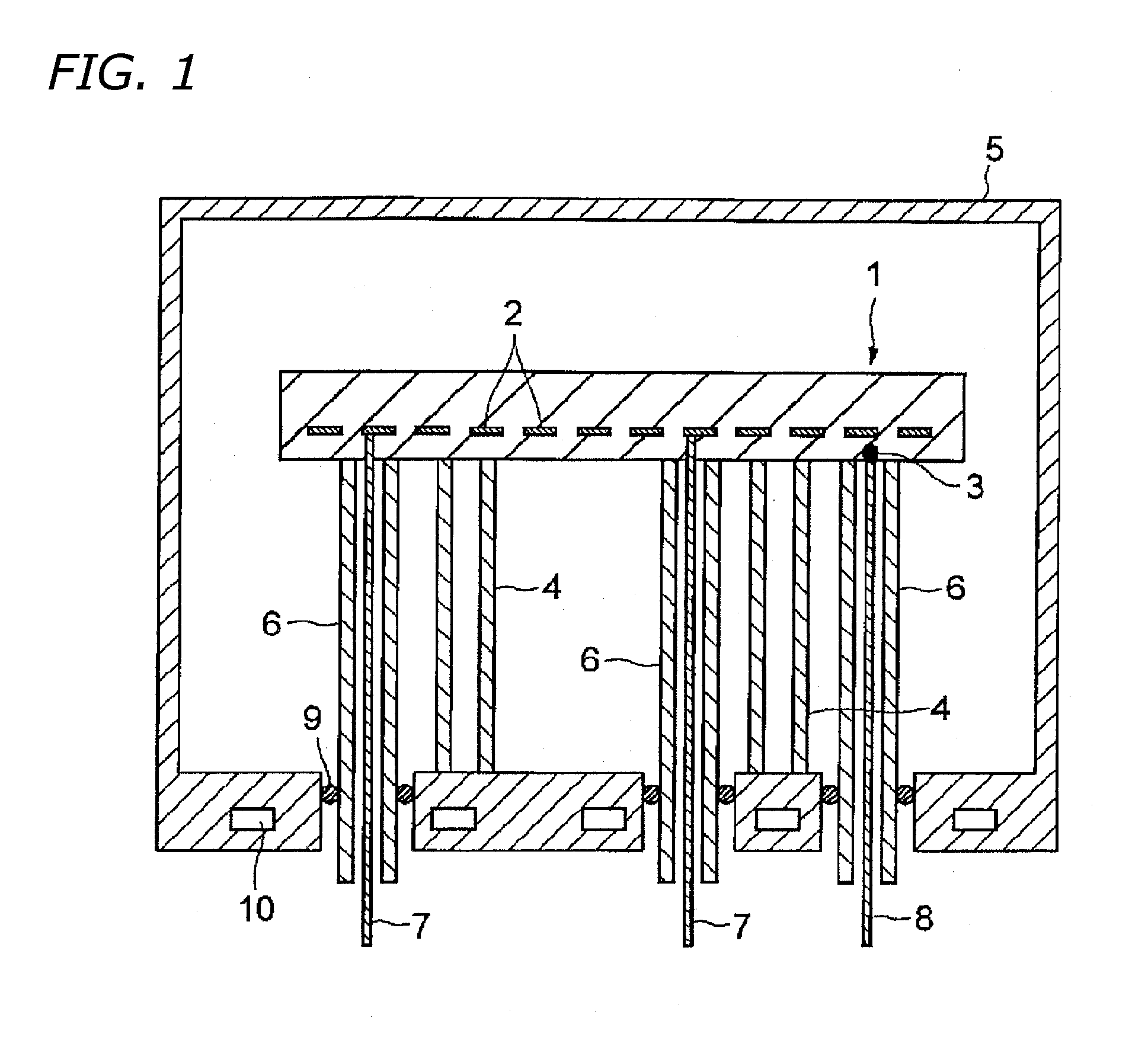
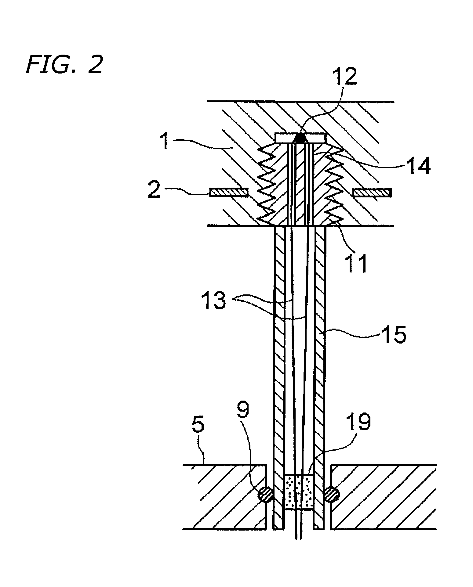
Temperature gauge and ceramic susceptor in which it is utilized

a technology of temperature gauge and susceptor, which is applied in the direction of heat measurement, instruments, coatings, etc., can solve the problems of pronounced temperature gradient, difficult accurate temperature measurement, and change in the direction of molecules moving thermally, so as to facilitate thermocouple replacement, short measurement temperature stabilizes, and easy replacement

Inactive Publication Date: 2004-10-21
SUMITOMO ELECTRIC IND LTD
View PDF18 Cites 185 Cited by
  • Summary
  • Abstract
  • Description
  • Claims
  • Application Information

AI Technical Summary

Benefits of technology

0057] As given by the present invention, a temperature gauge may be realized in which because the thermocouple is detachable, easy replacement of the thermocouple even if damaged is possible, and meanwhile in which, with heat from the temperature-gauging site on a gauging subject being readily transmitted to the temperature-gauging contact, time until the measurement temperature stabilizes is short. Accordingly, utilizing a temperature

Problems solved by technology

Nevertheless, in measuring temperature within the reaction chambers in semiconductor manufacturing equipment, accurate temperature measurement has been difficult because the behavior of gas molecules in the temperature-measuring component environs is altered on account of pressure fluctuations stemming from the introduction and discharge of reaction gases, drastically changing how the molecules move thermally.
Moreover, in cases in which the location where the temperature-measuring components are installed is remote from the wafer-heating face, the measurement temperature departing from the actual wafer temperature leads to a pronounced temperature gradient, which consequently has, depending on the case, invited circumstances in which the wafer is damaged by thermal stress.
A drawback with the ceramic susceptors set forth in the publications discussed above has been that with heat from the temperature-gauging site on the ceramic susceptor not being readily transmitted to the temperature-gauging contact, owing to the presence, surrounding the temperature-gauging contact that is on the tip o

Method used


Image

  • Temperature gauge and ceramic susceptor in which it is utilized
  • Temperature gauge and ceramic susceptor in which it is utilized
  • Temperature gauge and ceramic susceptor in which it is utilized

Examples


Embodiment Construction

[0048] 0.5 parts by weight yttria (Y.sub.2O.sub.3) as a sintering additive was added to 100 parts by weight aluminum nitride (AlN) powder, and was further combined with a predetermined amount of an organic extrusion binder; and after mixing these ingredients using a ball-mixing method the blend was granulated by spray-drying. The obtained granulated powder was molded by means of a uniaxial press into 2 disk forms whose post-sintering dimensions were 350 mm diameter.times.10 mm thickness. The 2 disk-shaped molded objects were degreased within a nitrogen atmosphere 900.degree. C. in temperature and furthermore sintered 5 hours at a temperature of 1900.degree. C. within a nitrogen atmosphere. The thermal conductivity of the AlN sinters produced was 170 W / mK. The entire surface of the AlN sinters was polished using a diamond abrasive.

[0049] A slurry in which a sintering additive and an ethyl-cellulose binder were added into and knead-mixed with tungsten powder was used to print a resist...


PUM

PropertyMeasurementUnit
Timeaaaaaaaaaa
Timeaaaaaaaaaa
Timeaaaaaaaaaa

Abstract

Temperature gauge, and ceramic susceptors and semiconductor manufacturing equipment utilizing the temperature gauge, in which the thermocouple may be easily replaced even if damaged, and in which heat from the temperature-gauging site is readily transmitted to the temperature-gauging contact, shortening time until the measurement temperature stabilizes. A temperature-gauging contact (12) in the tip of the thermocouple contacts, in an exposed-as-it-is state, a temperature-gauging site on a ceramic susceptor (1), and by means of a circular cylindrical-shaped retaining member (11) screwed into female threads in the ceramic susceptor (1) is detachably pressed upon and retained against the ceramic susceptor. Thermocouple lead lines (13), passing through a through-hole (14) in the retaining member (11), stretch from one end face to the other end face thereof. The retaining member may be provided with a flange having threaded holes and screwlocked into female screws in the ceramic susceptor.

Description

BACKGROUND OF INVENTION[0001] 1. Field of the Invention[0002] The present invention relates to temperature gauges for ceramic susceptors that are installed in semiconductor manufacturing equipment, and to ceramic susceptors, as well as semiconductor manufacturing equipment, utilizing the temperature gauges.[0003] 2. Description of the Background Art[0004] Ceramic susceptors (also called wafer holders) formed from an inorganic insulating material such as a ceramic of high thermal conductivity, and in which a resistive heating element is embedded, have been employed to date in semiconductor manufacturing equipment such as CVD devices and plasma CVD devices, for example, for uniformly heating wafers on which film-forming or like processes are carried out.[0005] In order to control the heating temperature by varying the amount of voltage and current applied to the resistive heating element, a plurality of terminals connected to the resistive heating element is furnished exposed on a fac...

Claims


Application Information

Patent Timeline
IPC IPC(8): G01K1/14C23C16/46G01K1/08G01K7/02H05B3/00
CPCG01K1/08
Inventor HASHIKURA, MANABUNAKATA, HIROHIKONATSUHARA, MASUHIROKUIBIRA, AKIRA
Owner SUMITOMO ELECTRIC IND LTD
Why Eureka
Try Eureka