Electrochromic mirrors and other electrooptic devices

a mirror and electrooptic technology, applied in the field of new and useful ec devices, can solve the problems of contaminating equipment, limiting back reaction, increasing the memory of ec devices, etc., and achieve the effects of low weight ec, low weight, and easy bending of thin substrates

Active Publication Date: 2004-11-25
AJJER
View PDF66 Cites 54 Cited by
  • Summary
  • Abstract
  • Description
  • Claims
  • Application Information

AI Technical Summary

Benefits of technology

0095] Low weight EC devices could be made using ionic liquids. As an example, for automotive mirrors, the substrate thickness could be in the range of 2.5 mm down to 0.5 mm. The two substrates used for making the cavity for the devices need not be the same thickness, they may even have different transparent conductors, e.g., one may be ITO coated and the other tin oxide coated such as TEC glass from Pilkington (Toledo, Ohio), or one of them may have a metallic conductor as described above. Thin substrates have also been used in EC mirrors (generally less than 1.5 mm in thickness). Further, the use of thin substrates has an advantage in non-planar mirrors. If mirrors such as convex or multi-radius are required (e.g., combination of flat and curved regions in the same mirror to eliminate blind spot (e.g. see U.S. Pat. No. 6,522,451), it is easy to bend thin substrates without causing creases and non-uniformities. Thin substrates as described in U.S. Pat. No. 6,195,194 may also be used in this invention.
0096] Also, use of preferred ionic liquids lends itself more favorably to the use of plastic substrates in electrooptic devices as these liquids are inert towards a large number of commercial polymers. Plastic substrates result in low weight and also better impact resistance. An additional advantage of using the ionic liquids is further protection of automotive interiors. In case of a mirror breakage or leakage, the electrolyte would not interact and blemish the interior plastic components such as dashboard. Further, if EC mirrors are made with plastic substrate in the rear and glass substrate in front, issues related to scratch resistance are avoided. When the back substrate is made of a plastic material then a metal coating or a stack comprising of a metal layer is deposited to act both as a reflector and as one of the two conductors in the EC cell cavity. U.S. Pat. No. 6,193,379 describes the use of cyclo-olefins as preferred material for use in EC devices, particularly EC mirrors. We have determined that it is not...

Problems solved by technology

This limits the back reaction and increases the memory of the EC device.
Since the conventional electrolytic solvents have high vapor pressures, some...

Method used


Image

  • Electrochromic mirrors and other electrooptic devices
  • Electrochromic mirrors and other electrooptic devices
  • Electrochromic mirrors and other electrooptic devices

Examples


example 1

Electrochromic Window Device Durability--UV Stabilizer A

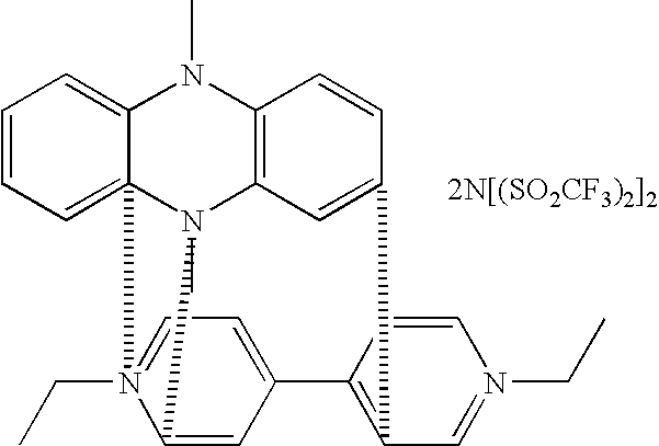
[0139] ITO substrates (15 .OMEGA. / sq) were cut into two 5.25".times.3.67" rectangular pieces. The active area of the device was about 92 sq.cm. In one piece, two holes about 3 mm in diameter were drilled near the corners of one of the diagonals to fill the electrolyte. The substrates were then washed, dried and stored in clean room conditions. An epoxy containing 102.5 micron glass bead spacers was dispensed around the edges of one of the substrates and the second substrate was placed on top of it to make a cavity such that the two substrates were staggered by 5 mm along the long side of the rectangular edge. This exposed edge on both substrates was later used to apply a busbar and make electrical connections. The epoxy seal was cured at 150.degree. C. The cavity was filled at room temperature with a liquid electrolyte containing 0.05M diethyl viologen bis(trifluoromethanesulfonyl)imide, 0.05M 5,10 dihydro-5-10-dimethyl phenazi...

example 2

Electrochromic Window Device Durability--UV Stabilizer B

[0142] Another set of electrochromic cells was prepared as described in Example 1. In this case, the UV stabilizer was substituted with 5 wt % of 2-cyano-3,3 diphenyl-acrylic acid ethyl ester in the same ionic liquid as Example 1. The electrochromic performance of the window device was determined as described in Example 1. These devices colored uniformly to a deep blue color and reversed to the original colorless state upon bleaching. Three devices were subjected to each of the tests as described in example 1. The results are shown in Tables 2a, 2b and 2c. The devices did not show any discoloration after any of the tests or when kept at -40.degree. C.

4 TABLE 2a % T (550 nm) Time (s) for 80% of full range Bleached Colored Time to color Time to bleach Initial 86.3 11.9 22.4 50.8 After 79,500 85.9 12.1 22.6 50.1 cycles

[0143]

5 TABLE 2b % T (550 nm) Time to 80% of full range Bleached Colored Time to color Time to bleach Initial 87.1...

example 3

Electrochromic Window Device Durability--Mixed UV Stabilizers

[0145] Another set of Electrochromic windows was prepared as described in Example 1. In this case, the UV stabilizers were 2 wt % of 2-4-dihydrobenzophenone and 5 wt % of 2-cyano-3,3 diphenyl-acrylic acid ethyl ester in the same ionic liquid as Example 1. The electrochromic performance of the window device was determined as described in Example 1. This device colored uniformly to a deep blue color and reversed to the original colorless state upon bleaching. Three devices were subjected to tests as described in Example 1. The results are shown in Tables 3a, 3b and 3c.

7 TABLE 3a % T (550 nm) Time (s) for 80% of full range Bleached Colored Time to color Time to bleach Initial 85.1 11.1 22.2 50.3 After 79,500 85.8 11.4 22.3 46.4 cycles

[0146]

8 TABLE 3b % T (550 nm) Time (s) for 80% of full range Bleached Colored Time to color Time to bleach Initial 85.8 10.8 22.3 49.2 After 1,000 kJ of 78.0 9.5 23.5 56.0 UV exposure

[0147]

9 TABL...


PUM

PropertyMeasurementUnit
Fractionaaaaaaaaaa
Angleaaaaaaaaaa
Electric potential / voltageaaaaaaaaaa

Abstract

This invention focuses on electrooptic devices and in particular on electrochromic devices with many aspects directed towards automotive EC mirrors. There are several ways to improve these products and their processing using this invention and some of the prominent ones are outlined below. This invention improves on the devices by disclosing new compositions for electrodes and methods of depositing them. It also addresses novel ways to provide busbars to power these devices in order to improve their performance. The device processing attributes and performance are also improved by adhesive compositions and solid electrolytes disclosed herein. In addition sensors are also disclosed which are novel for use in electrochromic mirrors. The invention also discloses how the electrolytes comprising ionic liquids have no adverse effect on attributes of commercial EC mirrors and often result in improved performance and/or feature enhancements.

Description

RELATED APPLICATIONS / CLAIM OF PRIORITY[0001] This application is related to and claims benefit of and priority to U.S. provisional application 60 / 452,332 filed on Mar. 5, 2003; 60 / 502,781 filed on Sep. 12, 2003 and 60 / 531,463 filed on Dec. 19, 2003, which are incorporated by reference herein.[0002] This invention is relates to the field of electrooptic (EO) devices particularly those EO devices which are electrochromic (EC). The application of these devices are in displays, windows, and variable reflectivity automotive mirrors and mirrors for other applications.[0003] Electrochromic devices are being increasingly used for automotive mirrors and have been suggested for many different applications. Recently, several publications suggest use of ionic liquids in electrolytes for EC devices, e.g. WO 03 / 003110, U.S. Pat. No. 6,365,301, Japanese application 08-329479 (publication number 10-168028). Published US patent application 20040021928 discloses EC devices using ionic liquids along w...

Claims


Application Information

Patent Timeline
IPC IPC(8): B60R1/08C09K9/00C09K9/02G02B5/08G02F1/15G02F1/161
CPCB60R1/088C09K9/02Y10T29/49002G02F1/161G02F1/1525C09J163/00
Inventor AGRAWAL, ANOOPTONAZZI, JUAN CARLOS LOPEZLECOMPTE, ROBERT S.CRONIN, JOHN P.
Owner AJJER
Why Eureka
Try Eureka