Precisely positioned nanowhiskers and nanowhisker arrays and method for preparing them

a nanowhisker array and precise positioning technology, applied in the direction of nanoinformatics, polycrystalline material growth, condensed vapor, etc., can solve the problems of inability to precisely position nanowhiskers and electronics/photonics components, difficult to control size and surface coverage separately, and large structure ranging in size, so as to reduce the mobility of the catalytic mass on the substrate surface

Inactive Publication Date: 2005-01-20
QUNANO
View PDF20 Cites 137 Cited by
  • Summary
  • Abstract
  • Description
  • Claims
  • Application Information

AI Technical Summary

Benefits of technology

A further important consideration is the initial shape and material constitution of the catalytic mass. The mass may include, in its initial constitution, separate regions of catalytic material, e.g. gold, and a material that will alloy with the catalytic material, e.g. indium, and assist in establishing supersaturation conditions for nanowhisker growth. This reduces the requirement for the mass to alloy with the substrate material in forming a seed particle, and hence increases the stability of the mass and its resistance to migration forces. As preferred, a sandwich of layers of catalytic / alloying / catalytic material is employed.
Further it has been found desirable to regulate activity of one or more elements of nanowhisker material in gaseous form around each site, so as to regulate growth of the nanowhisker. Where for example a III V semiconductor compound is being grown, it is preferred to regulate the activity of the group V element such as phosphorous, arsenic etc. If this further element is present in gaseous form around the nanowhisker site and has excess activity, then in order to provide more group III material to balance the reaction, this may force the catalytic mass to “search” for group III material by migration on the substrate surface. Likewise, if the activity of the group V material is too weak, then proper nanowhisker growth may not occur. For an MOVPE process, where cracking of the organometallic molecules takes place in the vicinity of the growth sites, this implies close control over reaction temperature, and gas volumes. For CBE however, the cracking of the group V molecules takes place in cracking cells, remote from the growth site, and there is more freedom in selecting a growth temperature and gaseous flow rates.

Problems solved by technology

This may result in structures ranging in size from small devices of atomic dimensions, to much larger scale structures for example on the microscopic scale.
With this technique, it is difficult to control the size and surface coverage separately.
The results were, in general, unsatisfactory for producing a structure with nanowhiskers sufficiently precisely positioned for electronics / photonics components, one reason being that the nanowhisker growth site could not be accurately localised, on account of the use of a thin film for forming the seed particle.
Selective area MOVPE growth (SA-MOVPE) has been used to develop two-dimensional photonic bandgap structures, but these appear of limited applicability.
However tubes are not ideal structures for forming areas of different refractive index.

Method used


Image

  • Precisely positioned nanowhiskers and nanowhisker arrays and method for preparing them
  • Precisely positioned nanowhiskers and nanowhisker arrays and method for preparing them
  • Precisely positioned nanowhiskers and nanowhisker arrays and method for preparing them

Examples


example 1

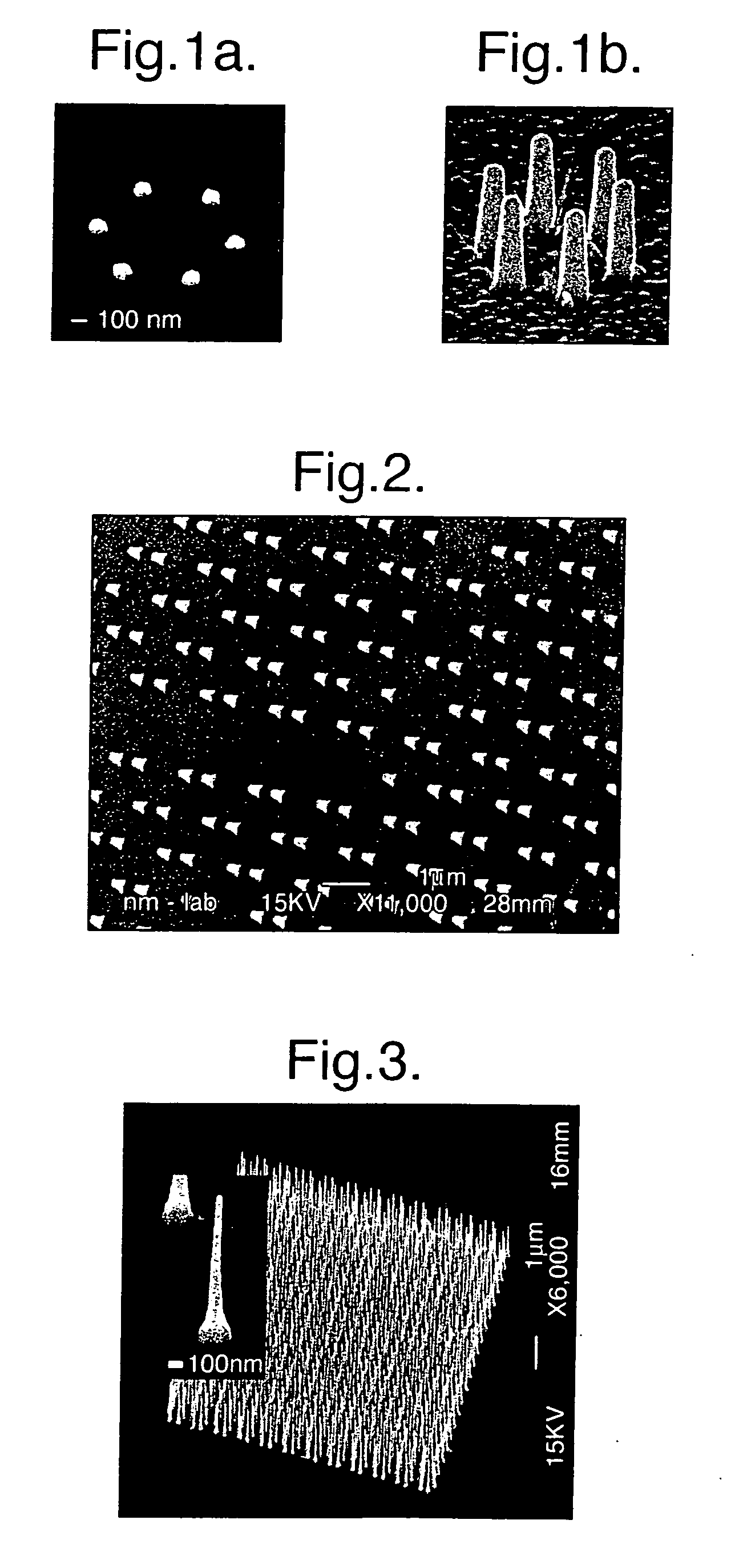
Samples were prepared from an n-type InP (111)B wafer. The (111)B substrate orientation was chosen since it is well known that the preferred wire growth direction is (111) B. The samples were cleaned on a spinner with acetone and isopropanol (IPA). They were then coated with poly(methylmethacrylate) (PMMA) photoresist and the disc pattern was transferred to the resist layer using a standard EBL technique. After development in methyl isobutyl ketone (MIBK) and rinsing in IPA, the samples were treated briefly with oxygen plasma to remove any resist residues from the exposed areas. After plasma treatment they were etched for 20 s in 4% hydrofluoric acid to remove surface oxide. The samples were then immediately transferred to a vacuum chamber where a gold film was deposited (thickness ranging from 17 to 45 nm and diameters of 125 nm) via thermal evaporation. The thickness was measured using a quartz crystal monitor. After metal lift-off by dissolution of the photoresist layer in hot a...

example 2

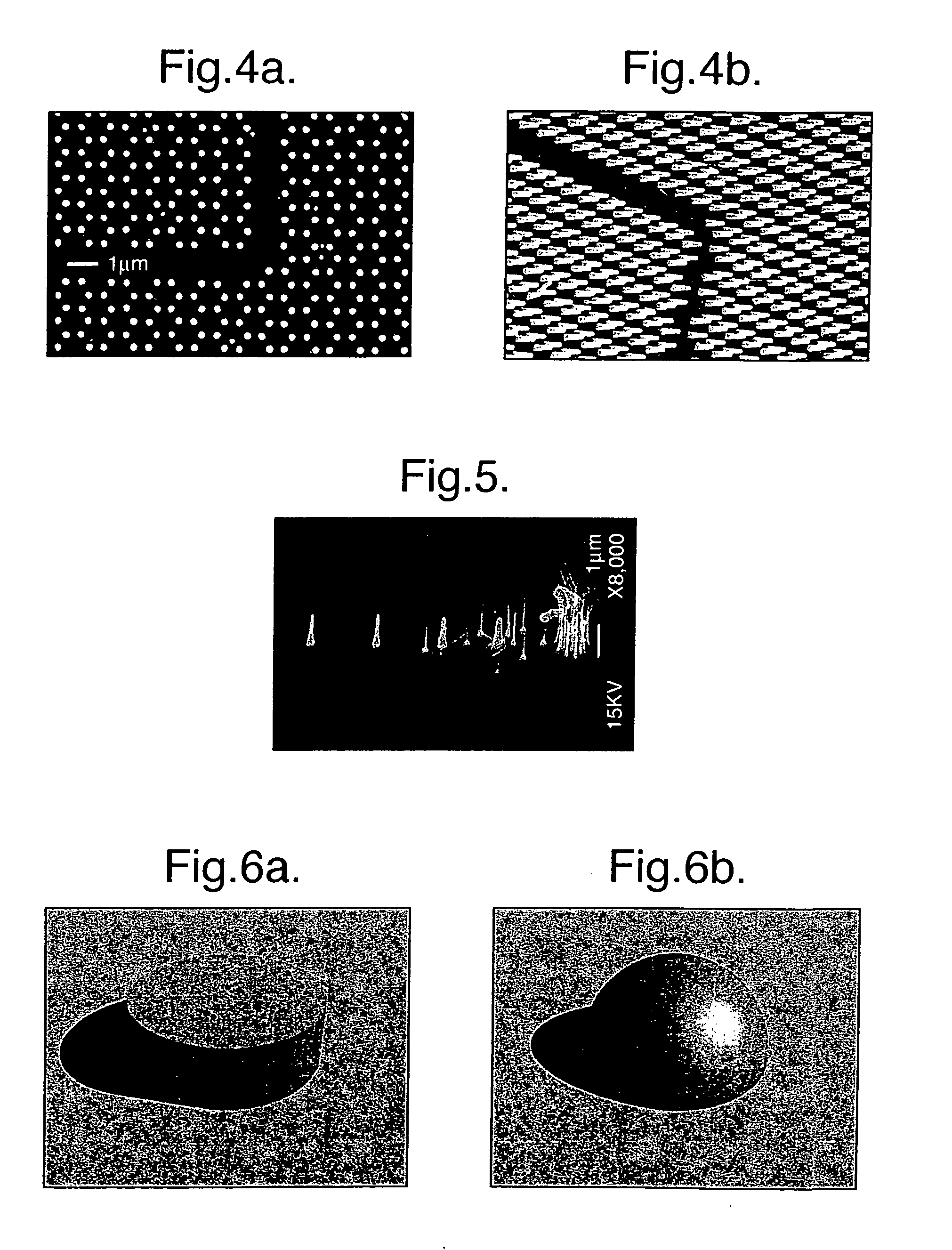
This example is based on nano-imprint lithography (NIL). NIL is in many respects capable of producing results comparable to those of electron beam lithography (EBL), but at a considerably lower cost and with a much higher throughput. NIL was used to pattern InP substrates with growth-catalyzing gold particles. Growth of vertically aligned InP nanowires then took place in a metal-organic vapor phase epitaxy (MOVPE) system via the vapor-liquid-solid (VLS) growth. The material of choice was InP, but the method is effective equally well with other III-V materials. The (111)B substrate orientation was used since the preferred growth direction of nanowires is <111>B, and vertically aligned arrays were desired.

The stamp for the nano-imprint process was made on a one-inch Si wafer using EBL and dry etching. A bi-layer of resist was used comprising ZEP520A7 / PMMA950k that was exposed at 35 kV with a probe current of 20 pA. After resist development, 30 nm of Chromium was thermally evap...

second embodiment

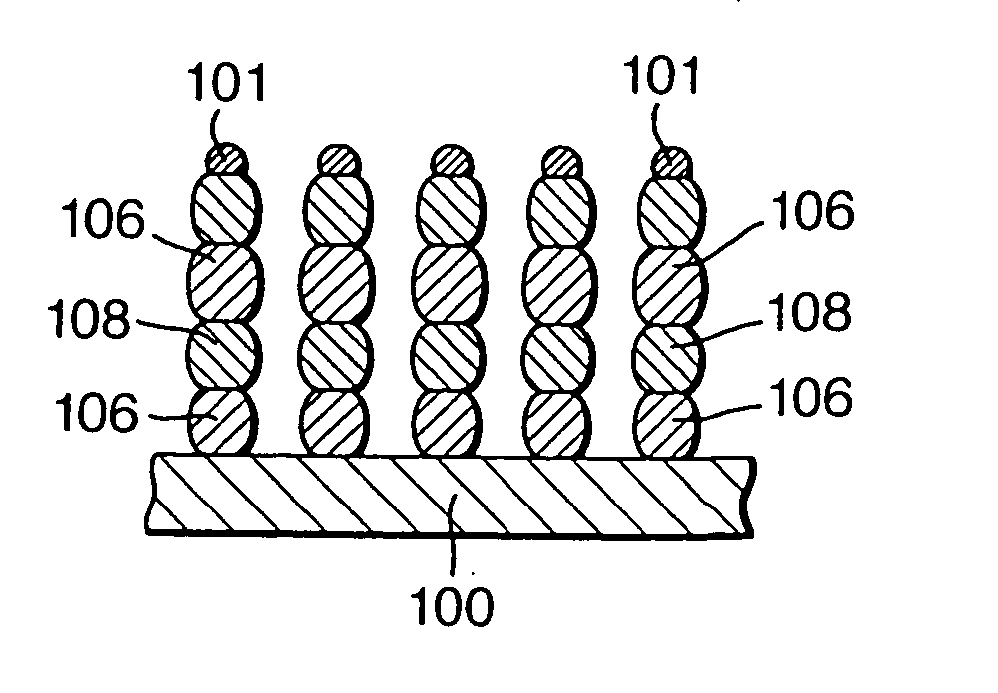
While it is possible by accurate and precise control over the operating parameters within a CBE process, to provide accurately positioned nanowhiskers within a nanowhisker array, an alternative and preferred technique, in accordance with the invention, is to provide a mask on the substrate surface which performs two functions, firstly that of preventing bulk growth on the surface, and secondly inhibiting movement of the catalytic particles. A mask in accordance with the invention is termed an epi-mask (epitaxy inhibitor).

Turning to FIG. 7a, a substrate 20 of gallium arsenide with a (111) surface has formed thereon an epi-mask 22. This may be an inorganic material such as silicon dioxide, or it may be an organic polymer material of which various types are commercially available.

As shown in FIG. 7b a photoresist material 24 is applied to layer 22 and is patterned for example using an electron beam. The photoresist material is then etched to produce a predetermined pattern as shown ...


PUM

PropertyMeasurementUnit
thicknessaaaaaaaaaa
sizeaaaaaaaaaa
diameteraaaaaaaaaa

Abstract

A nanoengineered structure comprising an array of more than about 1000 nanowhiskers on a substrate in a predetermined spatial configuration, for use for example as a photonic band gap array, wherein each nanowhisker is sited within a distance from a predetermined site not greater than about 20% of its distance from its nearest neighbour. To produce the array, an array of masses of a catalytic material are positioned on the surface, heat is applied and materials in gaseous form are introduced such as to create a catalytic seed particle from each mass, and to grow, from the catalytic seed particle, epitaxially, a nanowhisker of a predetermined material, and wherein each mass upon melting, retains approximately the same interface with the substrate surface such that forces causing the mass to migrate across said surface are less than a holding force across a wetted interface on the substrate surface.

Description

BACKGROUND OF THE INVENTION 1. Field of the Invention This invention relates generally to structures and devices produced by techniques of nanotechnology More specifically, the invention relates to such structures and devices incorporating at least one element, essentially in one-dimensional form, and that is of nanometer dimensions in its width or diameter, and that is produced by the so-called Vapour-Liquid-Solid (VLS) mechanism. For the purposes of this specification, such element will be termed a “nanowhisker”. 2. Brief Description of the Prior Art Nanotechnology covers various fields, including that of nanoengineering, which may be regarded as the practice of engineering on the nanoscale. This may result in structures ranging in size from small devices of atomic dimensions, to much larger scale structures for example on the microscopic scale. Commonly, such structures include nanostructures. Typically, nanostructures are devices having at least two dimensions less than abo...

Claims


Application Information

Patent Timeline
Patent Type & Authority Applications(United States)
IPC IPC(8): C30B11/00C30B11/12C30B29/40C30B29/60
CPCB82Y10/00B82Y30/00C30B29/605C30B11/12C30B29/40C30B11/00B82B3/00B82Y40/00C30B29/62
Inventor SAMUELSON, LARS IVAROHLSSON, BJORN JONASMARTENSSON, THOMAS M.I.
Owner QUNANO
Why Eureka
Try Eureka