

Ion source apparatus and cleaning optimized method thereof
a technology of ion source and cleaning method, which is applied in the direction of discharge tube general techniques, discharge tube cleaning, nuclear engineering, etc., can solve the problems of uncontrollable implanted amount, negative impact on the treatment of workpieces, and many problems, so as to improve the accuracy and efficiency of operation, and improve durability.
- Summary
- Abstract
- Description
- Claims
- Application Information
AI Technical Summary
Benefits of technology
Problems solved by technology
Method used
Image

Examples
Embodiment Construction
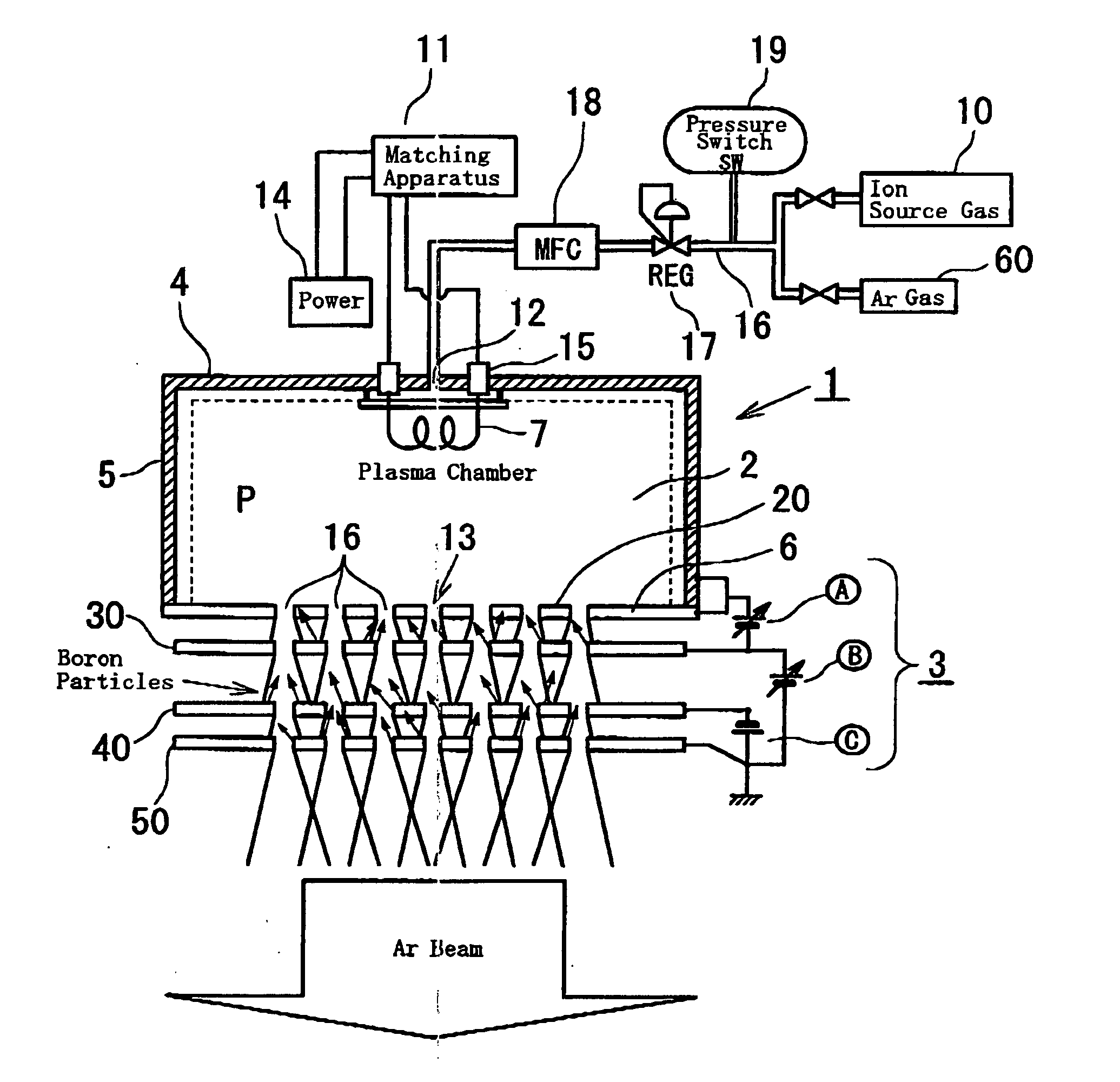
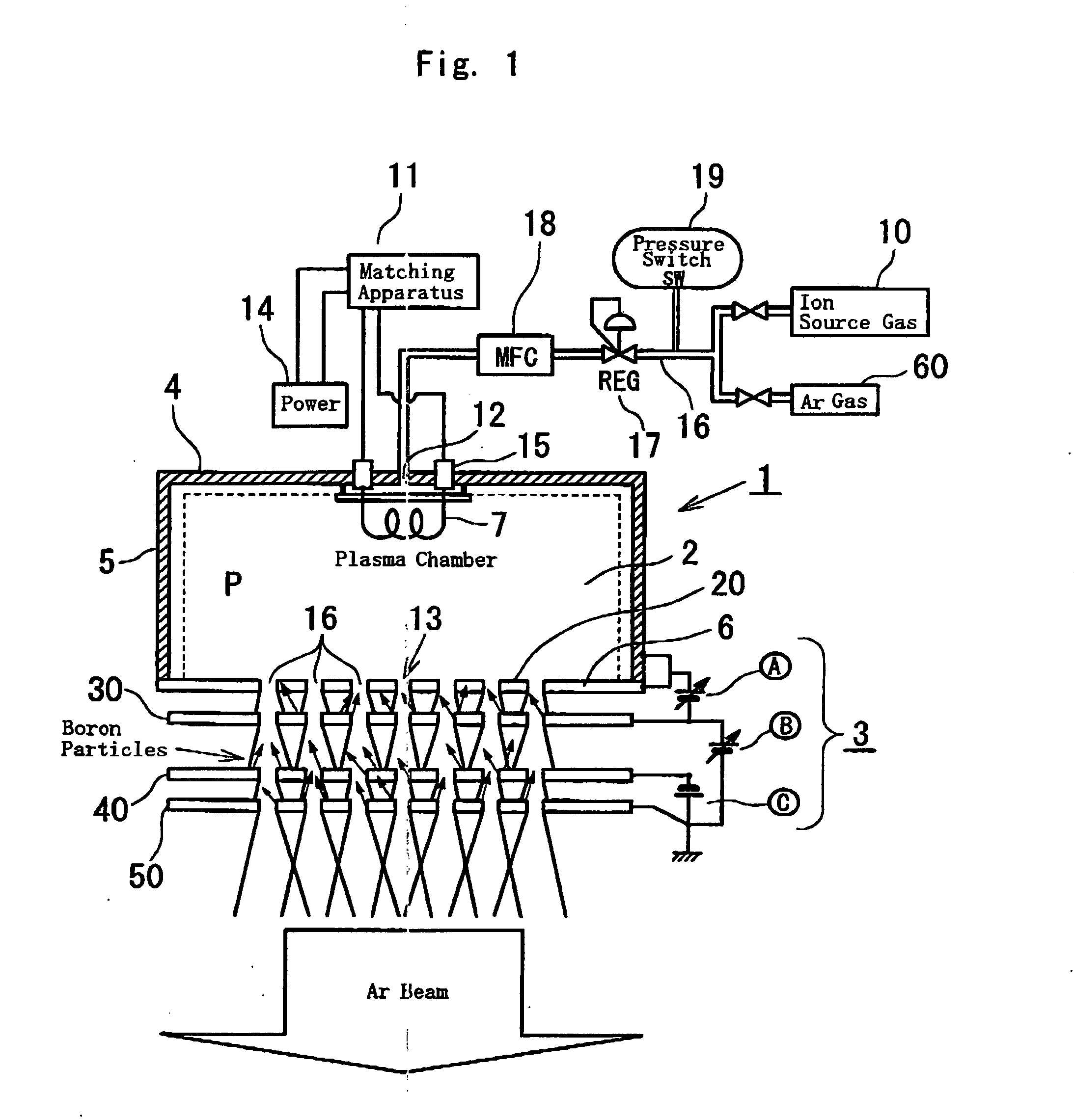
Embodiments of the present invention will be described with reference to the accompanying drawings. FIG. 1 is a schematic cross-sectional diagram of an ion source apparatus according to the present invention. This ion source apparatus 1 includes a plasma chamber 2 generating plasma (in plasma area P) by high-frequency discharge while confining the plasma, and an extraction electrode system 3 extracting ion beam from the plasma in the plasma chamber through electrical field.
The plasma chamber 2 is composed of a top wall 4 having an inlet opening 12 supplying ion source gas 10, side walls 5 provided with permanent magnets (not shown) at outer periphery thereof while integrally formed with the top wall 4, and a bottom wall 6 having an outlet opening 13. The top wall 4 has antenna installation opening 15 connecting to either a high-frequency wave generator or a microwave generator, which generates high-energy excitation signals to antenna element (antenna) 7 arranged in the plasma ch...
PUM
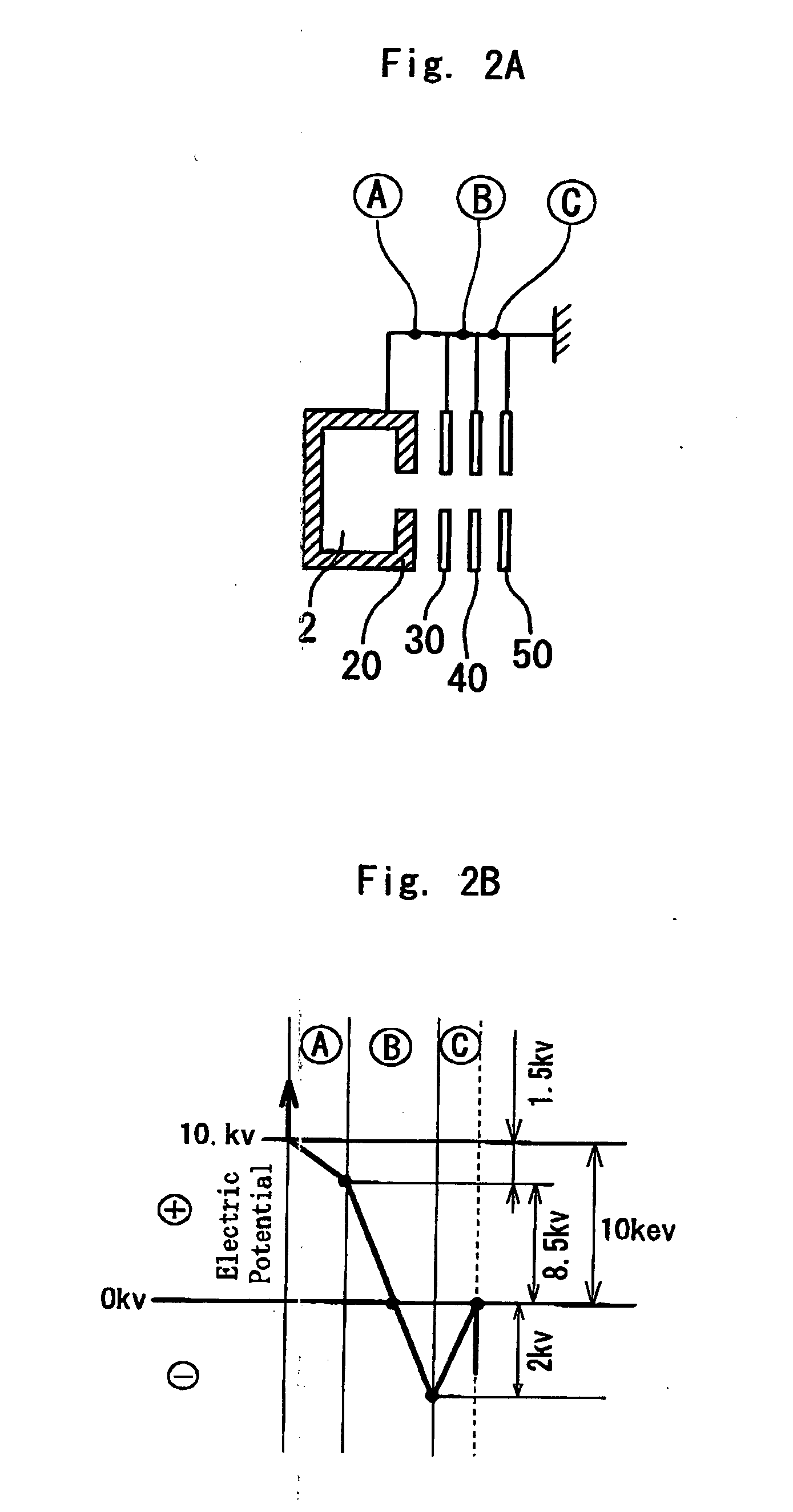
| Property | Measurement | Unit |
|---|---|---|
| electrical potential | aaaaa | aaaaa |
| power-supply voltages | aaaaa | aaaaa |
| power-supply voltages | aaaaa | aaaaa |
Abstract
Description
Claims
Application Information