Evaporation container and vapor deposition apparatus
a technology of evaporation container and vapor deposition apparatus, which is applied in vacuum evaporation coating, solid-state devices, coatings, etc., can solve the problems of increased radiation heat absorption in the upper portion of the container and inability to cool down the upper portion easily, and achieves superior throughput and stable operation for a long time.
- Summary
- Abstract
- Description
- Claims
- Application Information
AI Technical Summary
Benefits of technology
Problems solved by technology
Method used
Image
Examples
embodiment
[0046] Embodiment Mode 1
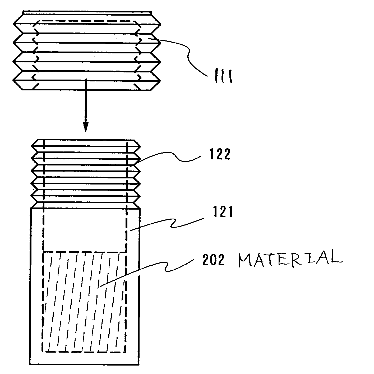
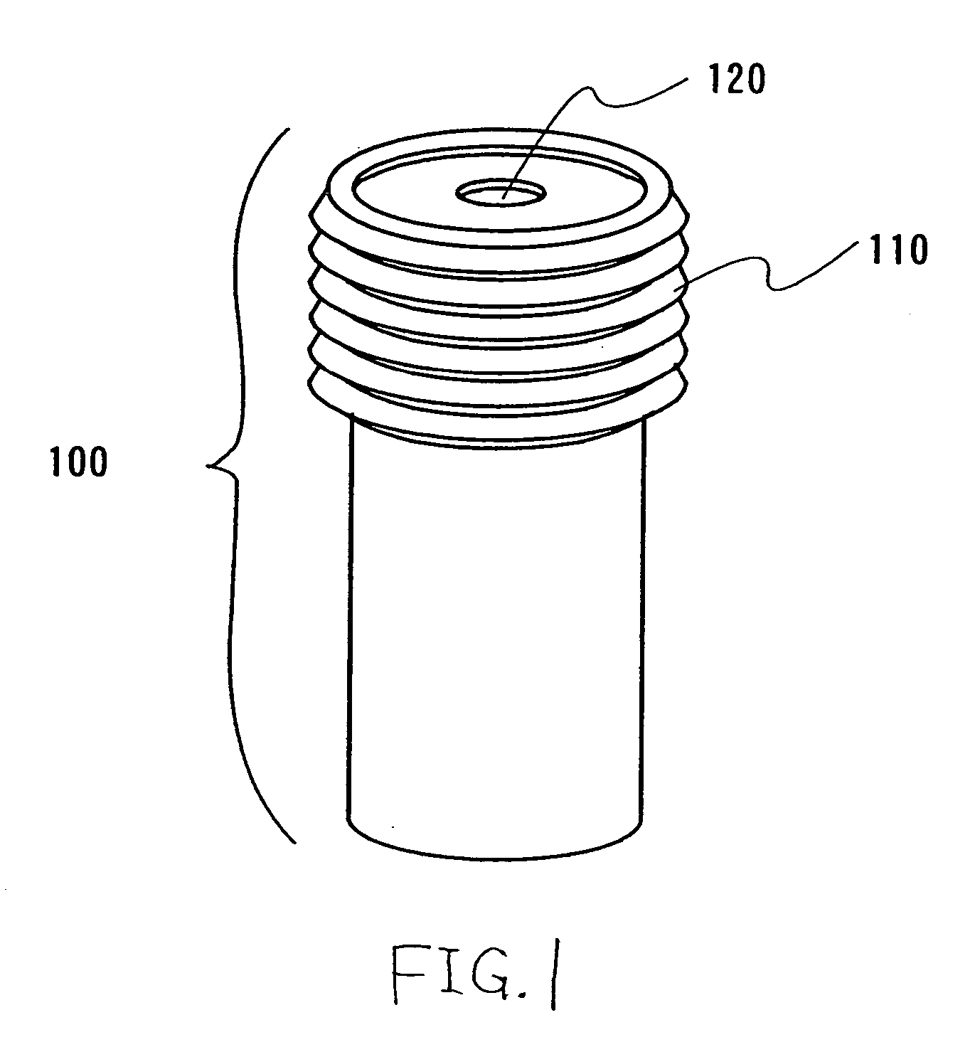
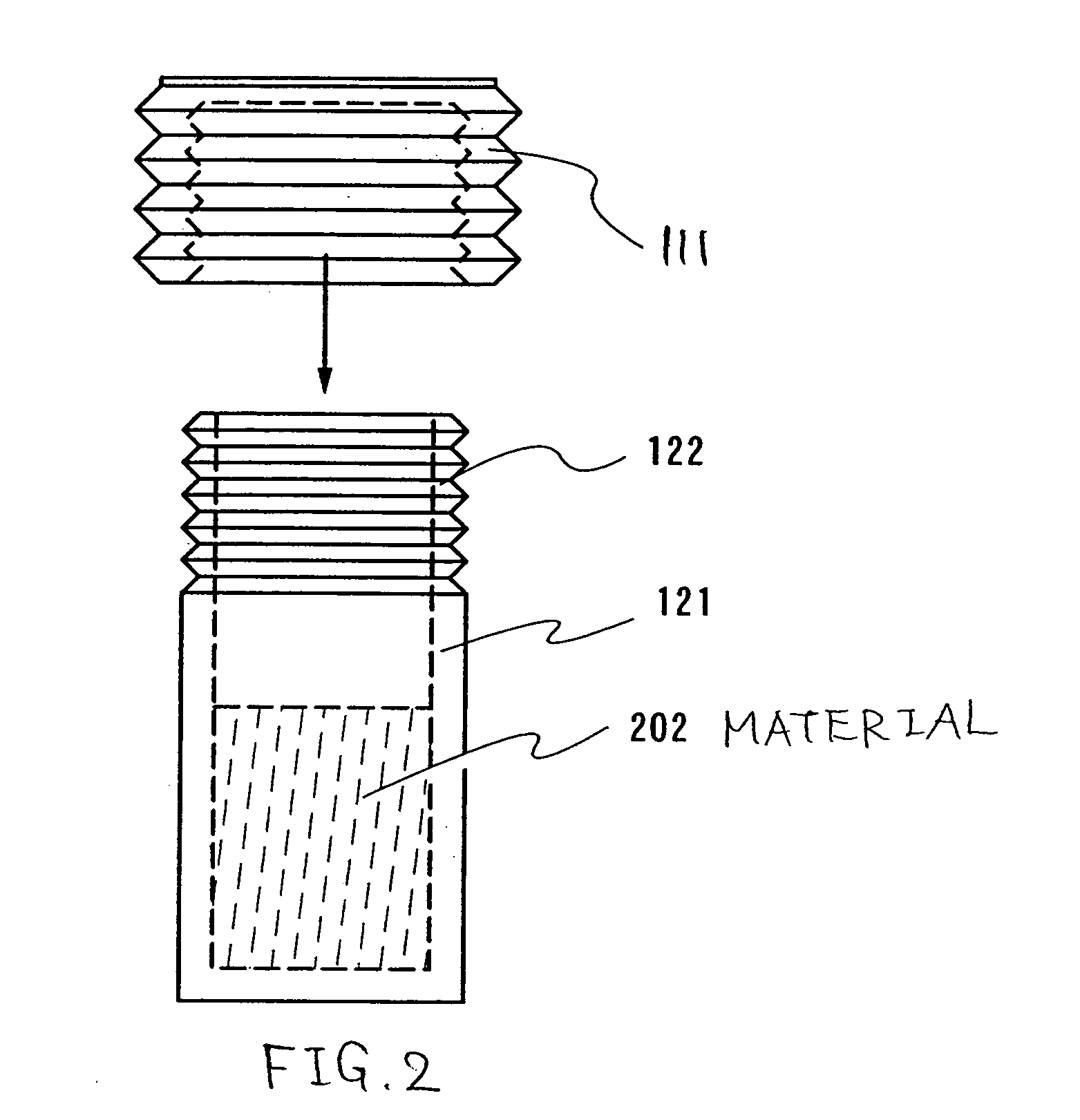
[0047]FIG. 1 shows a perspective view of a container 100 for the manufacturing device according to the present invention. The interior of the container 100 is hollow, and is filled with an evaporation material required for an organic EL element such as copper phthalocyanine (abbreviated as CuPc); 4,4′-bis-[N-(naphthyl)-N-phenyl-amino]-biphenyl (abbreviated as α-NPD); tris-8-quinolinolate aluminum complex (abbreviated as Alq3); and lithium fluoride (LiF). An accordion-shaped portion 110 including an accordion-shaped structure is provided at an upper portion of a side surface for the container 100, and an opening 120 for scattering evaporation particles is formed on a top surface of the container.
[0048] A material for the container 100 may be arbitrarily selected from materials as follows: tantalum; molybdenum; tungsten; titanium; boron nitride; more preferably, gold; silver; platinum; copper; aluminum; nickel; beryllium; silicon carbide; silicon nitride; boro...
embodiment mode 2
[0057] Embodiment Mode 2
[0058]FIG. 4A shows an overall view of an evaporation container 400 relating to the manufacturing device according to the invention. The evaporation container 400 is composed of a cylindrical body 401 with a bottom (a portion filled with an evaporation material), and a lid 403 including an opening 402. The interior of the container 400 is hollow, and is filled with an evaporation material required for an electroluminescence element such as copper phthalocyanine (abbreviated as CuPc); 4,4′-bis-[N-(naphthyl)-N-phenyl-amino]-biphenyl (abbreviated as 8-NPD); tris-8-quinolinolate aluminum complex (abbreviated as Alq3); lithium fluoride (LiF); and molybdenum oxide (abbreviated as MoOx). Vapor deposition is performed by using an evaporation source filled with a desired material in accordance with a layer to be vapor deposited.
[0059]FIG. 4B shows a state in which the container 400 is set in the evaporation source 404. The evaporation source is provided with a heatin...
embodiment 1
[0079] Embodiment 1
[0080]FIG. 8 shows a top view of a multichamber manufacturing device. The manufacturing device as depicted in FIG. 8 comprises chambers arranged for the purpose of improving the throughput.
[0081] The multi-chamber manufacturing device in FIG. 8 comprises: shutters 800a to 800n; a substrate loading chamber 801; a sealing and taking-out chamber 802; transporting chambers 803 and 804; film formation chambers 805, 806, and 807; container installation chambers 808a to 808d; a pretreatment chamber 809; a sealing-substrate-loading chamber 810; and a sealing chamber 811.
[0082] Hereinafter described is a process for fabricating a light emitting device by delivering a substrate on which an anode (a first electrode) and an insulator (a partition wall) for covering edges of the anode are previously provided, into a manufacturing device shown in FIG. 8. Note that in the case of manufacturing an active matrix light emitting device, a substrate is previously provided with a pl...
PUM
| Property | Measurement | Unit |
|---|---|---|
| Temperature | aaaaa | aaaaa |
| Diameter | aaaaa | aaaaa |
| Structure | aaaaa | aaaaa |
Abstract
Description
Claims
Application Information
 - R&D
- Intellectual Property
- Life Sciences
- Materials
- Tech Scout
- Unparalleled Data Quality
- Higher Quality Content
- 60% Fewer Hallucinations
Browse by: Latest US Patents, China's latest patents, Technical Efficacy Thesaurus, Application Domain, Technology Topic, Popular Technical Reports.
© 2025 PatSnap. All rights reserved.Legal|Privacy policy|Modern Slavery Act Transparency Statement|Sitemap|About US| Contact US: help@patsnap.com


