Hollow core photonic band gap infrared fibers

a technology of infrared fibers and hollow cores, which is applied in the field of hollow core photonic band gap chalcogenide fibers, can solve the problems of limited sensitivity of inability to use hollow core pbg silica fibers for fingerprint spectroscopy, and inability to transmit well. , to achieve the effect of increasing the sensitivity of sensing molecular species

Active Publication Date: 2005-02-03
THE UNITED STATES OF AMERICA AS REPRESENTED BY THE SECRETARY OF THE NAVY
View PDF6 Cites 58 Cited by
  • Summary
  • Abstract
  • Description
  • Claims
  • Application Information

AI Technical Summary

Benefits of technology

[0009] It is another object of this invention to increase sensitivity of sensing molecular species over evanescent technique by hundreds of times.

Problems solved by technology

The advantage of the fiber approach is that the sensing can now be done remotely but one drawback of the evanescent spectroscopy is that the technique has limited sensitivity since only a small fraction, i.e., a few percent, of the light propagates in the evanescent field.
However, it turns out that hollow core PBG silica fibers do not transmit well beyond about 2 μm since several percent of the light propagates in the microstructured region and this light is highly attenuated through multiphonon absorption in silica.
Hence, it is not possible to use silica PBG fibers to perform fingerprint spectroscopy in the IR beyond a wavelength of about 2 μm.

Method used


Image

  • Hollow core photonic band gap infrared fibers
  • Hollow core photonic band gap infrared fibers
  • Hollow core photonic band gap infrared fibers

Examples


example 1

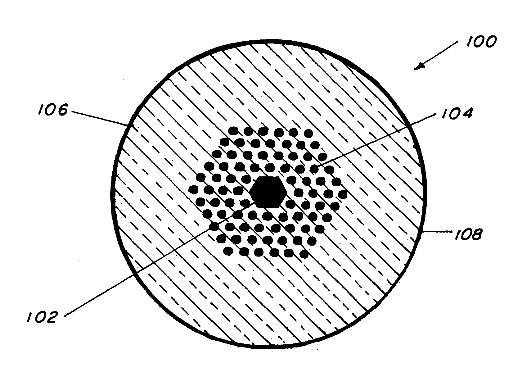
[0032] This example describes the method to fabricate a hollow core photonic band gap fiber from selenide-based chalcogenide glass with composition of As39 Se61.

[0033] The fabrication method included batching arsenic and selenium in pre-cleaned quartz ampoules using a glass box containing nitrogen with less than 100 ppb moisture and less than 1 ppm oxygen. The ampoules were evacuated to about 10−5 Torr and sealed using an oxygen-methane torch. The ampoules were then placed in a furnace and heated to about 800° C. and the batch allowed to react for about 10 hours and then further distilled to further purify the chemicals. Purification here is based on experience and purity of glass sought is up to about 0.5 dB / m and higher. The distillate was remelted for homogenization and then spun at about 2500 rpm while still molten in the ampoule. During cooling of the melt, while still rotating in the ampoule, the viscosity increased and a tube was formed, annealed and removed from the ampoule...

example 2

[0035] This example details the method to fabricate the hollow core photonic band gap fiber from sulfide-based chalcogenide glass with composition of As39 S6, but without the outer solid region that provides structural integrity to the fiber, particularly to the microstructured region.

[0036] The fiber was made by fabricating tubes, stretching by drawing them to micro-tubes, stacking, fusing and redrawing into fiber of the micro-structured sulfide preform, in a similar manner to Ex. 1 with the exception that there were no outer rods, i.e., micro-canes, used for mechanical integrity. Also, no Teflon®-coated mold was used but instead, the sulfide micro-tubes were stacked around a similar central sulfide micro-tube to form the preform and this was drawn into 95 μm outside diameter fiber. Again, high purity glass and high precision diameter tubes were not used nor was the gas pressure inside the tubes controlled during fiber drawing. Improvements in controlling these parameters will lea...

example 3

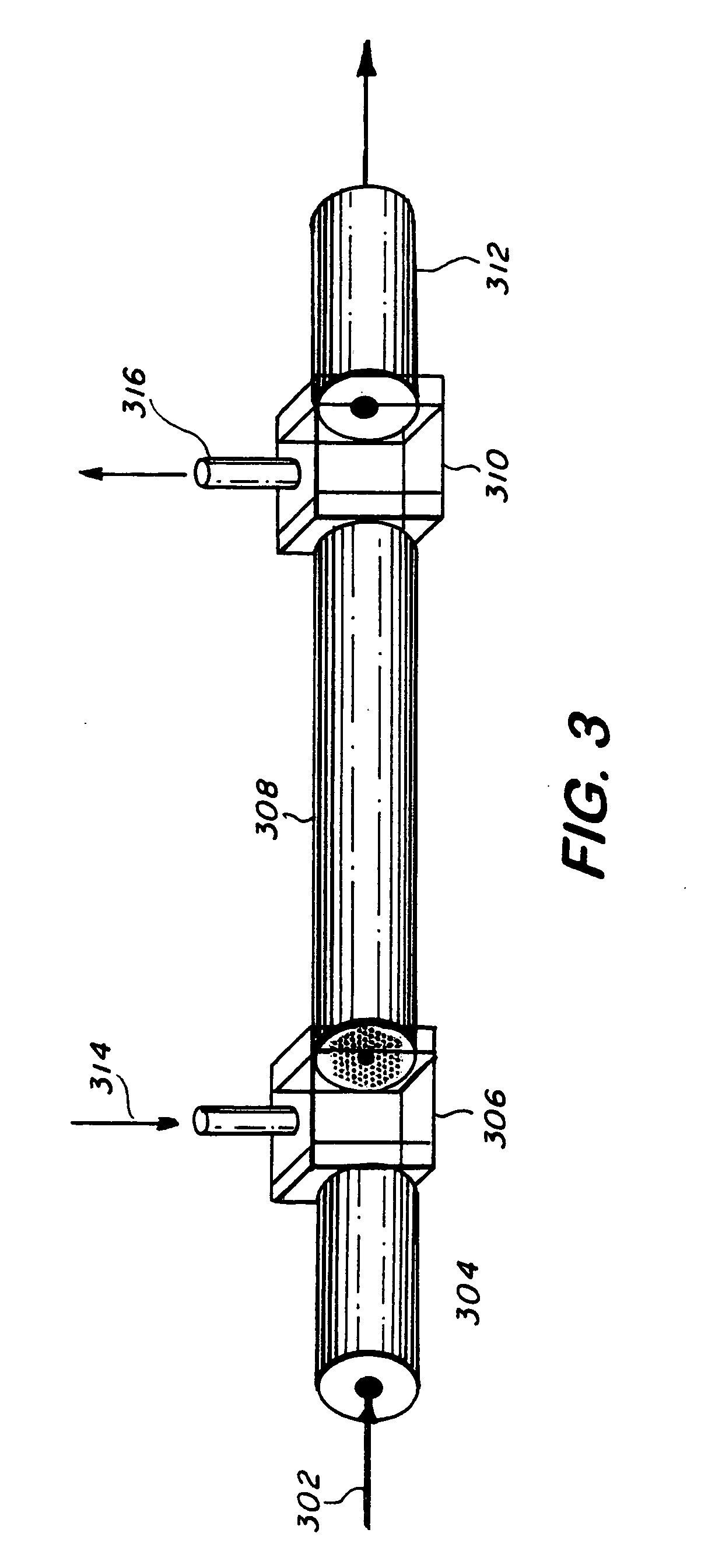
[0037] This example describes the use of a selenide fiber of this invention for chemical identification using remote infrared spectroscopy, using the system generally depicted in FIG. 3 but without coupling fibers 304 and 312.

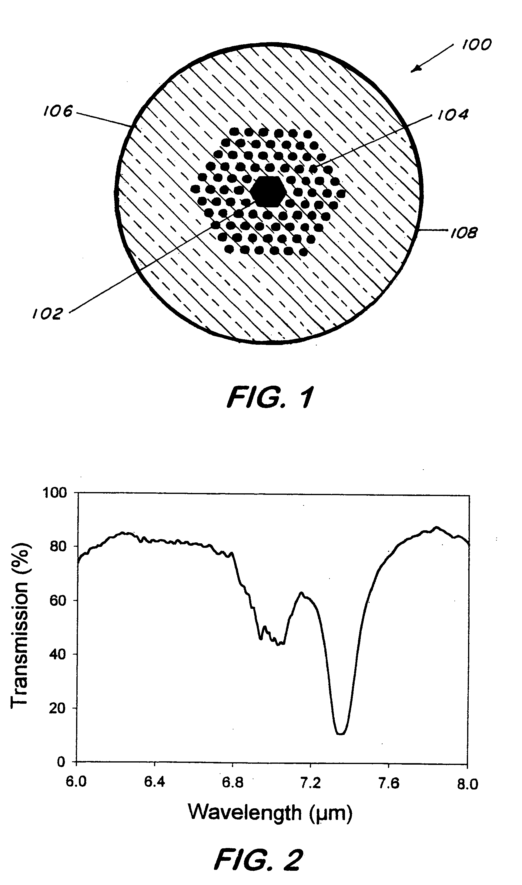
[0038] The sensing step includes the steps of directing infrared light into hollow core of the glass fiber of this invention, introducing analyte into the core of the fiber, transmitting the light and the analyte into the core of the fiber, and analyzing the light emanating from the fiber for presence of the analyte. Pursuant to the sensing method, hollow core photonic band gap fiber of Ex. 1 was coupled at one end to a source from an Analect Diamond 20 FTIR spectrometer. The distal end of the fiber was coupled to a liquid nitrogen HgCdTe detector. A small quantity of acetone was drawn into the hollow core through capillary action. The periodic holes were blocked-off with wax prior to this step. The infrared spectrum of acetone was recorded and the relative tr...


PUM

PropertyMeasurementUnit
outer diameteraaaaaaaaaa
thickaaaaaaaaaa
thickaaaaaaaaaa

Abstract

This invention pertains to a hollow core photonic band gap chalcogenide optical glass fiber and to a fabrication method for making the fiber. The fiber, which is 80-1000 microns in outside diameter, is characterized by a solid glass circumferential region and a structured region disposed centrally within the solid region, the structured region includes a hollow core of 1 micron to several hundreds of microns in diameter surrounded by a plurality of parallel hollow capillaries extending parallel to the core, the core being centrally and longitudinally located within the fiber. Ratio of open space to glass in the structured region is 30-99%. The fabrication method includes the steps of providing a mold, placing chalcogenide micro-tubes around the mold, stacking chalcogenide micro-canes around the stacked micro-tubes, fusing the micro-tubes and the micro-canes to form a preform, removing the mold and drawing the preform to obtain the fiber. In an alternative fabrication method, the fiber is made by extruding flowing chalcogenide glass through suitably made plate to form a preform and then drawing the preform to form the fiber.

Description

BACKGROUND OF THE INVENTION [0001] 1. Field of the Invention [0002] This invention pertains to hollow core photonic band gap chalcogenide fibers and to the method of making same. [0003] 2. Description of Related Art [0004] Practically every molecular species possesses a characteristic vibrational spectrum in the infrared wavelength region between about 2 and 12 μm. Consequently, chemicals can be clearly and definitely identified based on their unique infrared absorption spectra. In fact, this is called the “fingerprint region.” Detection and identification can be performed on liquids, gases and solids using traditional infrared (1R) spectrometers and Fourier Transform Infrared spectrometers. The chemicals can be detected using various modes including absorption and reflectance spectroscopy. [0005] Fiber optic based sensors have been developed using chalcogenide glass fibers. Chalcogenide fibers transmit in the fingerprint region and can be coupled to an IR spectrometer. In this case...

Claims


Application Information

Patent Timeline
Patent Type & Authority Applications(United States)
IPC IPC(8): B32B1/00C03B37/012C03C11/00C03C13/04G02BG02B6/02
CPCC03B37/0122C03B37/01274C03B2201/86C03B2201/88C03B2203/12C03B2203/14Y10T428/2913C03B2203/42C03C11/00C03C13/043G02B6/02328G02B6/02347Y10T428/265C03B2203/16
Inventor SANGHERA, JASBINDERAGGARWAL, ISHWARSHAW, L. B.PUREZA, P. C.KUNG, FREDCOLE, BRIAN
Owner THE UNITED STATES OF AMERICA AS REPRESENTED BY THE SECRETARY OF THE NAVY
Why Eureka
Try Eureka