
Electronic systems and component devices for macroscopic and microscopic molecular biological reaction, analyses, and diagnostics

a technology of electronic systems and components, applied in the field of molecular biology, can solve the problems of complex and time-consuming, many techniques are limited in their application, and require a high degree of accuracy, and achieve favorable reaction zones for reactant molecules

Inactive Publication Date: 2005-02-03
ADOR DIAGNOSTICS SRL
View PDF16 Cites 62 Cited by
  • Summary
  • Abstract
  • Description
  • Claims
  • Application Information

AI Technical Summary

Benefits of technology

"The invention is about a system that can control and carry out multiple reactions simultaneously, such as molecular biological reactions. The system can control the concentration of molecules and their reaction environment, which improves the speed and accuracy of the reactions. This technology can be used for various applications such as molecular biology research, diagnostics, and drug screening."

Problems solved by technology

They are often complex and time consuming, and generally require a high degree of accuracy.
Many a technique is limited in its application by a lack of sensitivity, specificity, or reproducibility.
For example, problems with sensitivity and specificity have so far limited the practical applications of nucleic acid hybridization.
Using the current nucleic acid hybridization formats and stringency control methods, it remains difficult to detect low copy number (i.e., 1-100,000) nucleic acid targets even with the most sensitive reporter groups (enzyme, fluorophores, radioisotopes, etc.) and associated detection systems (fluorometers, luminometers, photon counters, scintillation counters, etc.).
This difficulty is caused by several underlying problems associated with direct probe hybridization.
One problem relates to the stringency control of hybridization reactions.
Unfortunately, the application of these stringency conditions causes a significant decrease in the number of hybridized probe / target complexes for detection.
Another problem relates to the high complexity of DNA in most samples, particularly in human genomic DNA samples.
A third problem relates to the unfavorable hybridization dynamics between a probe and its specific target.
A fourth problem for most present hybridization formats is the high level of non-specific background signal.
These problems, either individually or in combination, lead to a loss of sensitivity and / or specificity for nucleic acid hybridization in the above described formats.
This is unfortunate because the detection of low copy number nucleic acid targets is necessary for most nucleic acid-based clinical diagnostic assays.
The enormous number of target nucleic acid sequences produced by the PCR reaction improves the subsequent direct nucleic acid probe techniques, albeit at the cost of a lengthy and cumbersome procedure.
Both formats have the fundamental problems of direct probe hybridizations and additional difficulties related to multiplex hybridizations.
This inability to achieve “sequencing by hybridization” by a direct hybridization method lead to a so-called “format 3”, which incorporates a ligase reaction step.
However, Southern did not address how to achieve optimal stringency condition for each oligonucleotide on an array.
The results showed many mismatches.
Like Southern, Fodor et al., did not address the underlying problems of direct probe hybridization, such as stringency control for multiplex hybridizations.
These problems, together with the requirement of a large quantity of the simple 12-mer target, indicate severe limitations to this SBH format.
Regardless of the format, all current micro-scale DNA hybridizations and SBH approaches do not overcome the underlying problems associated with nucleic acid hybridization reactions.
They require very high levels of relatively short single-stranded target sequences or PCR amplified DNA, and produce a high level of false positive hybridization signals even under the most stringent conditions.
In the case of multiplex formats using arrays of short oligonucleotide sequences, it is not possible to optimize the stringency condition for each individual sequence with any conventional approach because the arrays or devices used for these formats can not change or adjust the temperature, ionic strength, or denaturants at an individual location, relative to other locations.
This results in a large number of non-specific and partial hybridizations and severely limits the application of the device.
This is particularly troublesome for SBH, which requires a large number of short oligonucleotide probes.
However, the use of direct current (DC) fields is prohibitive for their work.
However, the dielectrophoresis process requires a very high frequency AC (1 MHz) voltage and a low conductivity medium.
While these techniques can orient DNA molecules of different sizes along the AC field lines, they cannot distinguish between hybridization complexes of the same size.
Even though of very high probe densities, such a “passive” micro-hybridization approaches have several limitations, particularly for arrays directed at reverse dot blot formats, for base mismatch analysis, and for re-sequencing and sequencing by hybridization applications.
This places limitations on the length, GC content and secondary structure of the capture probes.
Third, for many applications large target fragments, including PCR or other amplicons, can not be directly hybridized to the array.
Fourth, for passive hybridization the rate is proportional to the initial concentration of the target fragments in the solution, therefore, very high concentrations of target is required to achieve rapid hybridization.
Fifth, because of difficulties controlling hybridization conditions, single base discrimination is generally restricted to capture oligomers sequences of 20 bases or less with centrally placed differences (see, e.g., Chee '96; Guo,Z, et.al., Nucleic Acid Research, V.
However, for at least the reasons stated above, these techniques have been proved deficient.
Despite the long-recognized need for effective technique, no satisfactory solution has been proposed previously.

Method used


Image

  • Electronic systems and component devices for macroscopic and microscopic molecular biological reaction, analyses, and diagnostics
  • Electronic systems and component devices for macroscopic and microscopic molecular biological reaction, analyses, and diagnostics
  • Electronic systems and component devices for macroscopic and microscopic molecular biological reaction, analyses, and diagnostics

Examples


example 1

Semipermeable Matrix Preparation

Streptavidin-Agarose Preparation

2.5% glyoxal agarose (BioWhittaker) was prepared in water per manufacturer's instructions. Agarose solution was incubated at 60° C. until ready to use. Streptavidin (Boehringer Mannheim) was dissolved in 100 mM sodium phosphate, pH 7.4 to a final concentration of 5 mgs / ml. Fresh 200 mM sodium cyanoborohydride in sodium phosphate, pH 7.4 was prepared. Streptavidin-agarose (4:1),was mixed and incubated at 60° C. for 2 minutes.

Gels were cast in either cut down Pasteur pipettes (˜5 mm diameter gel tubes) or 1 mm holes drilled into an ABS plastic plate (for the device shown in FIG. 10). Pipettes received 150 microliters, and sample plate holes received 5 microliters of SA-GA. After gelling, cyanoborohydride solution was pipetted over the top of the gels and the reduction reaction allowed to proceed for 2 hrs at room temperature or 16 hrs at 4° C.

Streptavidin-Polyacrylamide Preparation

PEG-Streptavidin Synthesis:

A ...

example 2

Electronic Hybridization and Dehybridization

For this example, the gel tube apparatus illustrated in FIG. 12 was used with an agarose / streptavidin SPM synthesized as described in Example 1.

Attachment of Capture Oligonucleotides (Specific Binding Entity):

Upper and lower buffer reservoirs were filled with 50 mM histidine, pI. Specific capture ATA5 (5′ biotin-GATGAGCAGT TCTACGTGG [SEQ. ID NO. 1]) or nonspecific ATA4 (5′biotin-GTCTCCTTCC TCTCCAG [SEQ. ID NO.2]) oligos were pipetted onto the top of the gel (5 microliters 500 nM in 50 mM histidine, pI, 10% glycerol). The lower buffer reservoir was biased positive and the oligos electrophoresed into the gel for 2 minutes, 20V using a Bio-Rad PowerPac 1000 power supply. Reversing the bias for 2 minutes effected an electronic wash. Gel tubes were then rinsed in histidine buffer, pI.

Hybridization:

Upper buffer chamber was filled with 50 mM histidine, pI and the lower buffer was filled with 100 mM histidine, pH 5. BodipyTR labeled RCA5...

example 3

SNP Mutation Discrimination in H-Ras System

For this example, the gel tube apparatus illustrated in FIG. 12 was used with an agarose / streptavidin SPM synthesized as described in Example 1.

Capture:

Ras G wild type and Ras T mutant captures are loaded as per Example 2. (RAS G:5′ biotin-CACACCOGCG GCGCC [SEQ. ID NO.4], RAS T: 5′ biotin-CACACCGTCG GCGCC [SEQ. ID NO. 5])

Hybridization:

As per example 2 using BodipyTR labeled Ras C reporter complement (5′ btr-GGCGCCGCCG GTGTG [SEQ. ID NO. 6].

Stringency / Dehybridization:

As per example 2.

Results:

Hybridization signal was observed on both wild type and mutant gel caps before reversing the bias. By reversing the bias, mismatch signal was selectively removed after biasing 5 minutes, 70 V in 20 mm sodium phosphate, pH 7.4. A discrimination ratio of 79:1 was obtained.

Initial IntensityFinal IntensityWild type16479mutant1341


PUM

PropertyMeasurementUnit
electric potentialaaaaaaaaaa

Abstract

This invention pertains to the design, fabrication, and uses of an electronic system which can actively carry out and control multi-step and multiplex reactions in macroscopic or microscopic formats. In particular, these reactions include molecular biological reactions, such as nucleic acid hybridizations, nucleic acid amplification, sample preparation, antibody / antigen reactions, clinical diagnostics, combinatorial chemistry and selection, drug screening, oligonucleotide and nucleic acid synthesis, peptide synthesis, biopolymer synthesis, and catalytic reactions. A key feature of the present invention is the ability to control the localized concentration of two or more reaction-dependant molecules and their reaction environment in order to greatly enhance the rate and specificity of the molecular biological reaction

Description

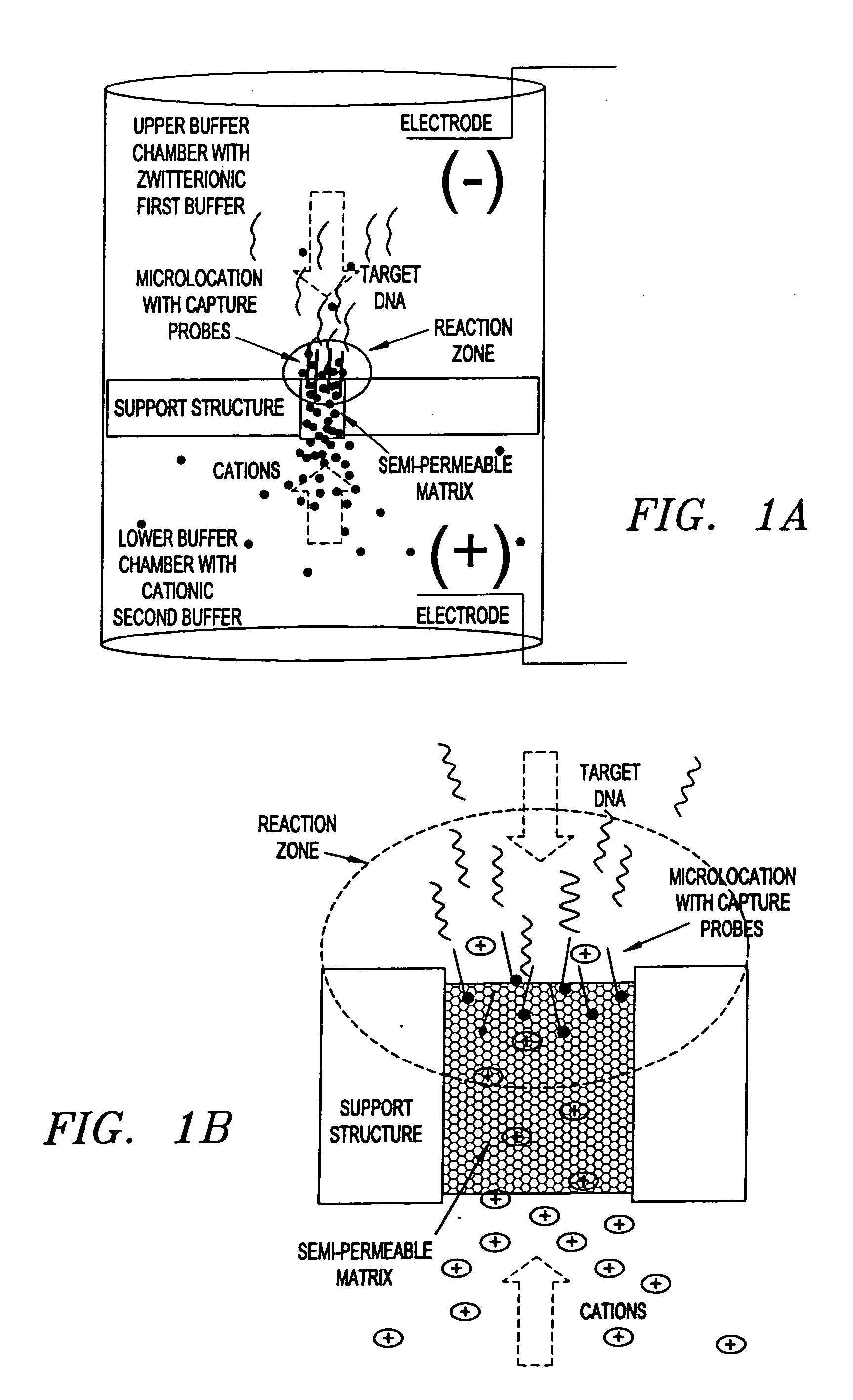
BRIEF DESCRIPTION This invention pertains to the design, fabrication, and uses of an electronic system which can actively carry out and control multi-step and multiplex reactions in macroscopic or microscopic formats. In particular, these reactions include molecular biological reactions, such as nucleic acid hybridizations, nucleic acid amplification, sample preparation, antibody / antigen reactions, clinical diagnostics, combinatorial chemistry and selection, drug screening, oligonucleotide and nucleic acid synthesis, peptide synthesis, biopolymer synthesis, and catalytic reactions. A key feature of the present invention is the ability to control the localized concentration of two or more reaction-dependant molecules and their reaction environment in order to greatly enhance the rate and specificity of the molecular biological reaction. RELATED APPLICATION INFORMATION The following applications and patents are incorporated by reference herein in their entirety: application Ser. No....

Claims


Application Information

Patent Timeline
Patent Type & Authority Applications(United States)
IPC IPC(8): B01J19/00B01L3/00G01N33/53G01N33/543G01N33/551
CPCB01J19/0046Y10S977/924B01J2219/00576B01J2219/00585B01J2219/00596B01J2219/00605B01J2219/0061B01J2219/00621B01J2219/0063B01J2219/00644B01J2219/00659B01J2219/00677B01J2219/00689B01J2219/00695B01J2219/00713B01J2219/0072B01J2219/0074B01L3/502753B01L2300/0819B01L2400/0415B82Y30/00G01N33/5308G01N33/54353G01N33/5438G01N33/551B01J2219/00527
Inventor EDMAN, CARL F.TU, EUGENEGURTNER, CHRISTIANWESTIN, LORELEIHELLER, MICHAEL J.
Owner ADOR DIAGNOSTICS SRL
Learn More