Hydrogen production with photosynthetic organisms and from biomass derived therefrom

a technology of photosynthetic organisms and biomass, which is applied in the direction of biochemistry apparatus and processes, separation processes, disinfection, etc., can solve the problems of no rate-limiting step in the aqueous phase, no commercial success to date, and limited efficiency

Inactive Publication Date: 2005-03-24
GREENFUEL TECHNOLOGIES CORPORATION
View PDF46 Cites 225 Cited by
  • Summary
  • Abstract
  • Description
  • Claims
  • Application Information

AI Technical Summary

Problems solved by technology

In addition, algae are capable of growing in saline waters that are unsuitable for agriculture.
Although photosynthesis is fundamental to the conversion of solar radiation into stored biomass, efficiencies can be limited by the limited wavelength range of light energy capable of driving photosynthesis (400-700 nm, which is only about half of the total solar energy).
The dissolution of NO in the aqueous phase is believed to be the rate-limiting step in this NOX removal process.
Each program took a different approach but because of various problems, addressed by certain embodiments of the present invention, none has been commercially successful to date.
A major obstacle for feasible algal bio-regeneration and pollution abatement has been an efficient, yet cost-effective, growth system.
The ponds require low capital input; however, algae grown in open and uncontrolled environments result in low algal productivity.
The open pond technology made growing and harvesting the algae prohibitively expensive, since massive amounts of dilute algal waters required very large agitators, pumps and centrifuges.
Furthermore, with low algal productivity and large flatland requirements, this approach could, in the best-case scenario, be applicable to only 1% of U.S. power plants.
On the other hand, the MITI approach, with stricter land constraints, focused on very expensive closed algal photobioreactors utilizing fiber optics for light transmission.
In these controlled environments, much higher algal productivity was achieved, but the algal growth rates were not high enough to offset the capital costs of the expensive systems utilized.
These bioreactors, when oriented horizontally, typically require additional energy to provide mixing (e.g., pumps), thus adding significant capital and operational expense.
Photobioreactors that do not utilize solar energy but instead rely solely on artificial light sources can require enormous energy input.
Since no precisely defined flow lines are reproducibly formed, it can be difficult to control the mixing properties of the system which can lead to low mass transfer coefficients poor photomodulation, and low productivity.
However, control over the flow patterns within an air lift reactor to achieve a desired level of mixing and photomodulation can still be difficult or impractical.
In addition, because of geometric design constraints, during large-scale, outdoor algal production, both types of cylindrical-photobioreactors can suffer from low productivity, due to factors related to light reflection and auto-shading effects (in which one column is shading the other).
The value of hydrogen in producing clean, abundant energy cannot be overestimated.
Not only are these sources non-renewable and in limited supply, but current gasification and reforming technologies for producing hydrogen from such sources produce the greenhouse gas CO2 as a primary by-product, as well as other pollutant gases, e.g. NOx, which are typically released to the atmosphere.
Thus, current hydrogen production technologies substantially attenuate and undermine the promise of hydrogen as a clean, abundant source of energy for the future.

Method used


Image

  • Hydrogen production with photosynthetic organisms and from biomass derived therefrom
  • Hydrogen production with photosynthetic organisms and from biomass derived therefrom
  • Hydrogen production with photosynthetic organisms and from biomass derived therefrom

Examples


example 1

Mitigation of CO2 and NOx with a Three-Photobioreactor Module Including Three Triangular Tubular Photobioreactors

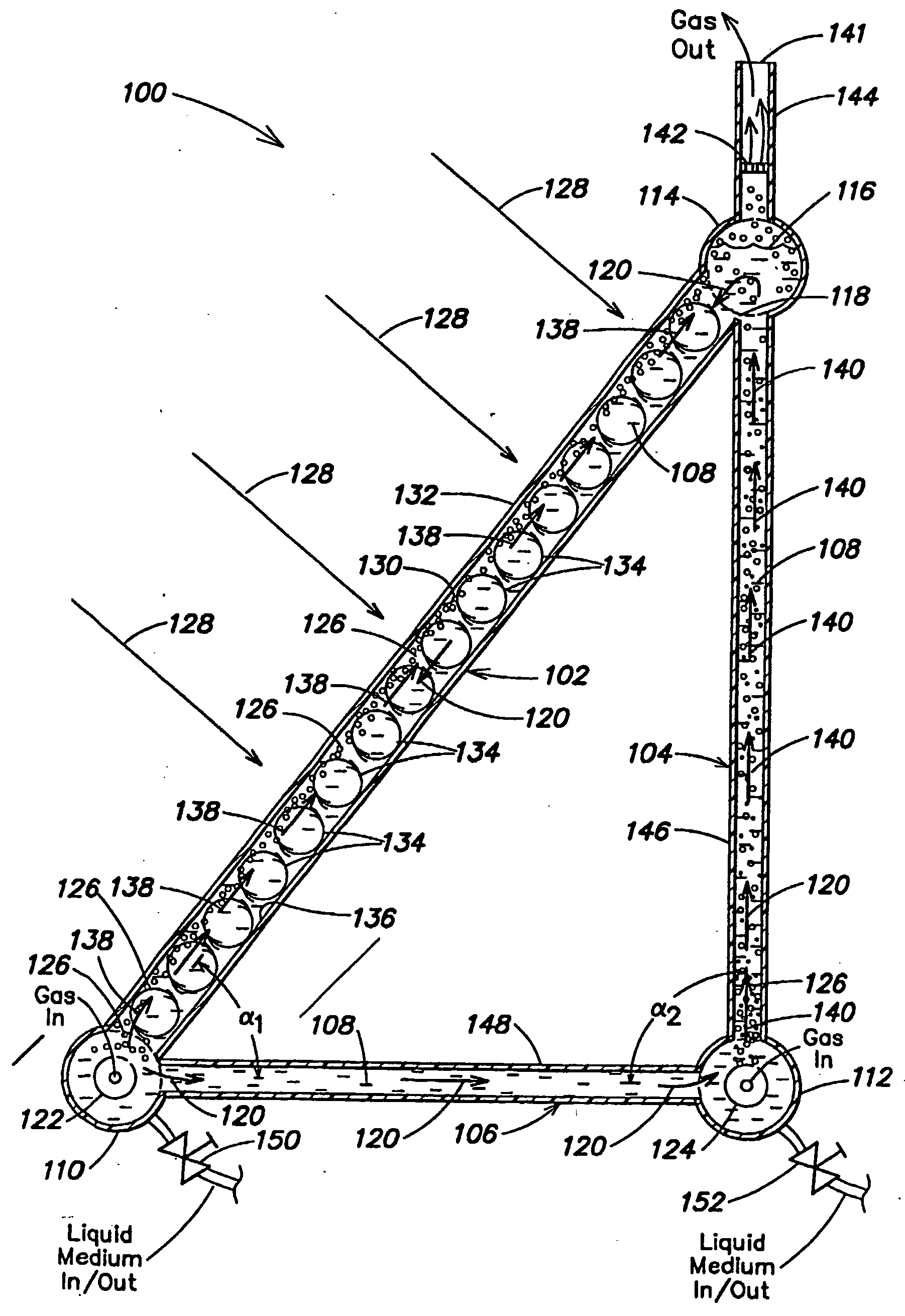
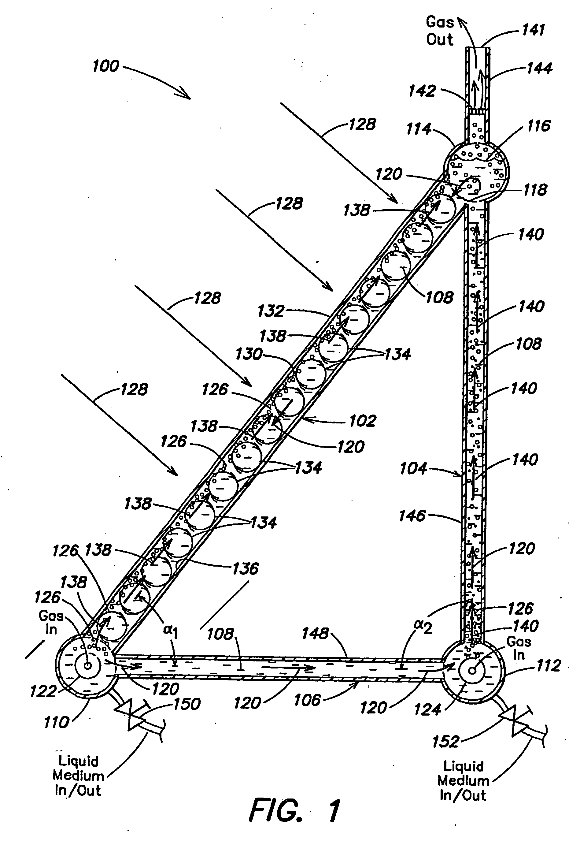
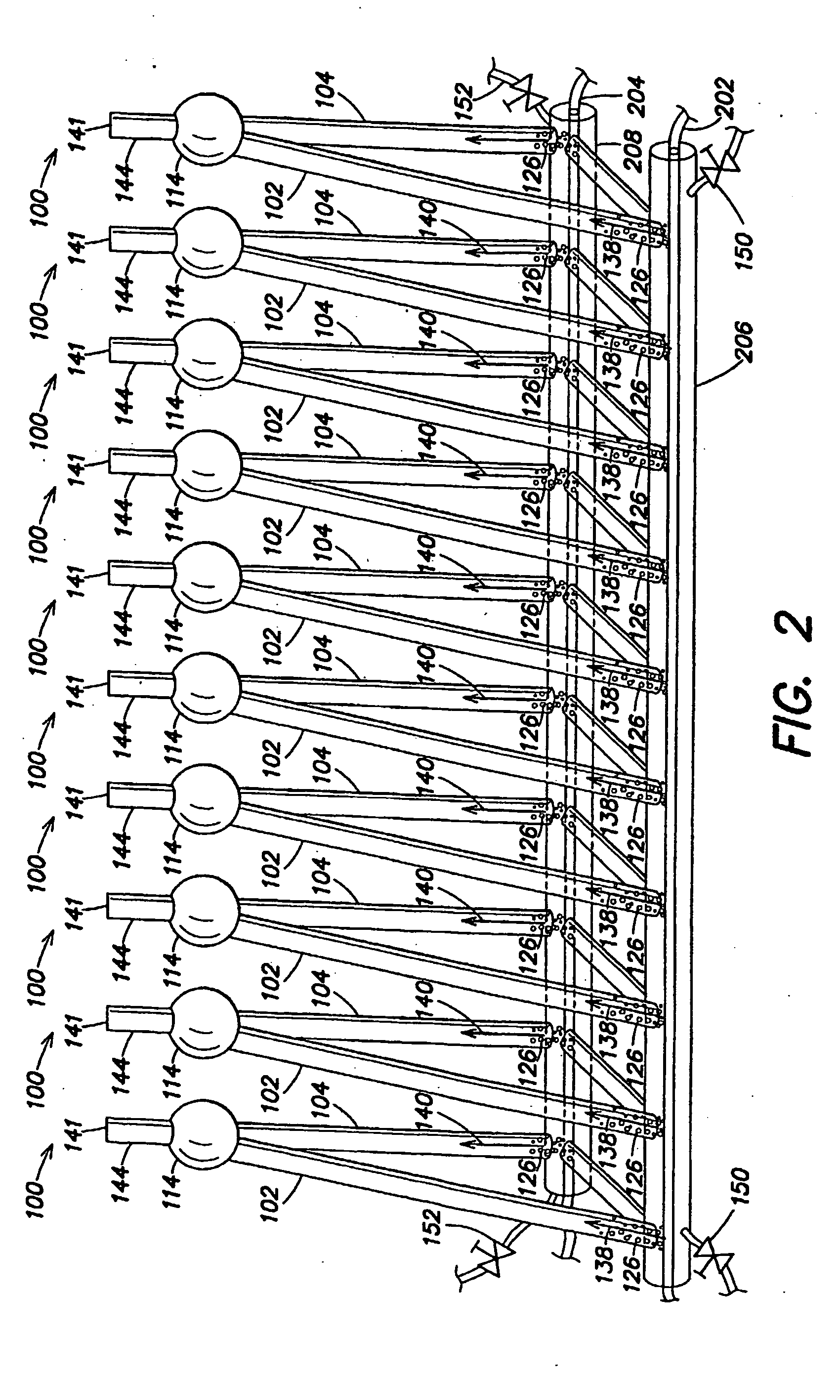
Each photobioreactor unit of the module utilized for the present example comprised 3 tubes of essentially circular cross-section constructed from clear polycarbonate, assembled as shown in FIG. 1, with α1=about 45 degrees and α2=about 90 degrees. In this essentially triangular configuration, the essentially vertical leg was 2.2 m high and 5 cm in diameter; the essentially horizontal leg was 1.5 m long and 5 cm in diameter; and the hypotenuse was 2.6 m long and 10 cm in diameter. The photobioreactor module comprised 3 adjusted units arranged in parallel, similarly as illustrated in FIG. 2. This bioreactor module has a footprint of 0.45 m2

A gas mixture (certified, AGA gas), mimicking flue gas composition was used (Hiroyasu et al., 1998). The total gas flow input was 715 ml / min per each 10 liter photobioreactor in the module. Gas distribution to the spargers injecting ga...

examples 2-5

Photobioreactor Arrays for Mitigation of Power Plant Flue gas Pollutants and Production of Algal Biomass

All examples below relate to a 250 MW, coal-fired power plant with a flue gas flow rate of 781,250 SCFM, and coal consumption of 5,556 tons / d. Flue gas contains CO2 (14% vol), NOx (250 ppm) and post-scrubbing level of SOx (200 ppm, defined in the US 1990 Clean Air Act Amendment). 12 h / d sunlight is assumed, as is a mean value of solar radiation of 6.5 kWh / m2 / d, representing typical South-Western US levels (US Department of Energy). Algal solar efficiency of 20% is assumed, based on performance data of Example 1 and literature values (Burlew, 1961). Daytime algal CO2 and NOx mitigation efficiency is 90% and 98% (respectively), and at night 0% and 75% (respectively), based on Example 1 performance and literature values (Sheehan et al., 1998; Hiroyasu et al., 1998). Biodiesel production potential is 3.6 bbl per ton of algae (dry weight) (Sheehan et al., 1998). System size and perfo...

example 6

Use of a Small-Scale Automated Photobioreactor Cell Culture System for Preconditioning of Algal Cultures to High Intensity Illumination and Photomodulation

A culture of the microalgae Dunaliella parva (UTEX.) was grown and adapted, as described below, using a small-scale photobioreactor system similar to that illustrated in FIGS. 8a-8f. The medium used was the same modified F / 2 described in Example 1. The cell culture module had an internal culture volume of about 10 ml. Gas exchange was performed utilizing a silicone-coil gas exchanger, similar to gas exchanger 862 of FIG. 8a, which was fed a gas mixture comprising 8% CO2 (balance air) at a rate of 100 ml / min. Flow rate of liquid medium in the perfusion loop was about 1 mmin net forward flow. The culture was stirred using magnetic stir bars rotated at about 40 RPM. The culture was maintained at room temperature (about 25° C.). Cell density was monitored with a spectrophotometer, and culture dilutions were made as necessary to main...


PUM

PropertyMeasurementUnit
angleaaaaaaaaaa
angleaaaaaaaaaa
transparentaaaaaaaaaa

Abstract

Certain embodiments and aspects of the present invention relate to photobioreactor apparatus designed to contain a liquid medium comprising at least one species of photosynthetic organism therein, and to methods of using the photobioreactor apparatus as part of a hydrogen production process and system configured to generate hydrogen with and / or from biomass produced in the photobioreactor apparatus. In certain embodiments, the disclosed hydrogen production systems and methods, photobioreactor apparatus, methods of using such apparatus, and / or gas treatment systems and methods provided herein can be utilized as part of an integrated combustion and hydrogen production method and system, wherein photosynthetic organisms utilized within the photobioreactor are used to at least partially remove certain pollutant compounds contained within combustion gases, e.g. CO2 and / or NOx, and are subsequently harvested from the photobioreactor, processed, and utilized as a fuel source for generating hydrogen and / or as a fuel source for a combustion device (e.g. an electric power plant generator and / or incinerator).

Description

FIELD OF INVENTION The invention relates generally to hydrogen production using photosynthetic organisms and / or from biomass derived therefrom, and in certain embodiments, from biomass produced by photobioreactors operated for the treatment of gases, such as flue gases. BACKGROUND OF THE INVENTION In the United States alone, there are 400 coal burning power plants representing 1,600 generating units and another 10,000 fossil fuel plants. Although coal plants are the dirtiest of the fossil fuel users, oil and gas plants also produce flue gas (combustion gases) that may include CO2, NOX, SOX, mercury, mercury-containing compounds, particulates and other pollutant materials. Photosynthesis is the carbon recycling mechanism of the biosphere. In this process, photosynthetic organisms, such as plants, synthesize carbohydrates and other cellular materials by CO2 fixation. One of the most efficient converters of CO2 and solar energy to biomass are algae, the fastest growing plants on ear...

Claims


Application Information

Patent Timeline
Patent Type & Authority Applications(United States)
IPC IPC(8): B01D53/85
CPCB01D53/85C12M21/02C12M23/58C12M43/06C12M41/00C12M41/48C12M29/06Y02P20/59Y02A50/20
Inventor BERZIN, ISAAC
Owner GREENFUEL TECHNOLOGIES CORPORATION
Why Eureka
Try Eureka