Two-stage catalytic process for recovering sulfur from an H2S-containing gas stream

a catalytic process and gas stream technology, applied in the field of sulfur recovery processes, can solve the problems of over-utilization, low sulfur recovery, and over-exceeding the market value of gas, and achieve the effects of optimizing the conversion of h2s, reducing the so2 level in the product gas, and improving operability and stability

Inactive Publication Date: 2005-08-18
CONOCOPHILLIPS CO
View PDF8 Cites 20 Cited by
  • Summary
  • Abstract
  • Description
  • Claims
  • Application Information

AI Technical Summary

Benefits of technology

[0025] Employing a short contact time reactor and suitable catalysts, the process allows the direct oxidation of H2S to take place on gas streams containing a much wider range of H2S concentrations than is presently possible with conventional H2S direct oxidation processes and operating at temperatures ranging up to about 1,500° C. By optimizing H2S conversion and catalytically reducing any incidental SO2 that is formed, the equilibrium constraint of the Claus reaction (Reaction 2) is removed and the conversion of H2S to sulfur in the direct oxidation step is urged forward toward completion. Achieving a high level of conversion in the initial direct oxidation stage (Reaction 4) allows the elimination of the intermediate catalytic stages of the Claus reaction. By reducing the incidental SO2 to S0 in a second stage, the need for SO2 conversion or absorption from the tail gas is lessened or obviated, which constitutes a considerable improvement in operability and stability over conventional Claus processes. By manipulating the air or oxygen that is fed in the first stage and the reducing gas that is fed in the second stage, the conversion of H2S is optimized and the SO2 level in the product gas is minimized.

Problems solved by technology

Removal of H2S from H2S-containing gases is a major focus of current research because utilization of the enormous supply of natural gas existing in underground reservoirs all over the world is hindered due to the presence of naturally-occurring H2S along with the methane and other light hydrocarbons that make up natural gas.
Some natural gas formations contain only a relatively small concentration of H2S, yet even those types of natural gas wells typically remain shut-in today because the cost of removal of the H2S using existing methods and apparatus exceeds the market value of the gas.
A further deterrent to full utilization of H2S-containing natural gas resources is the corrosive effect of the H2S component of liquefied natural gas on the transportation pipes and storage vessels that are needed to bring the H2S-containing natural gas from remote locations to existing sulfur treatment plants.
Sulfur recovery was low and the highly exothermic reaction was difficult to control.
The Claus-type processes are not suitable for use in cleaning up hydrogen or light hydrocarbon gases (such as natural gas) that contain H2S, however.
Not only is the hydrocarbon content lost in the initial thermal combustion step of the Claus process, but carbon, carbonyl sulfide and carbon disulfide byproducts cause catalyst fouling and dark sulfur.
Moreover, carbonyl sulfide is difficult to convert to elemental sulfur.
The major problem with the Claus process is the inherent equilibrium constraint of the Claus reaction caused by the necessity of generating the SO2 intermediate.
Usually these catalytic oxidation processes are limited to Claus tail gas operations or sulfur recovery from streams that have very low H2S content (i.e., about 1-3%).
Low concentration H2S streams will not produce enough energy release from oxidation to sustain a flame as in a thermal reactor stage.
The existing catalytic oxidation technologies are thus limited to low concentration H2S-containing streams using non-refractory lined vessels.
Existing processes are also limited in the amount of sulfur that can be handled because the heat transfer equipment needed to remove the heat of reaction becomes extremely large due to the low temperature differential between the process and the coolant streams.
These processes are also limited in the amount of sulfur recovered due to the heat removal constraints at low temperatures and the need to maintain low temperatures to keep the liquid from boiling.
For at least these reasons, existing direct oxidation processes have not proved to be viable substitutes for the Claus process in most industrial applications.
As mentioned above, conventional direct oxidation methods are applicable to sour gas streams containing relatively small amounts of H2S and large amounts of hydrocarbons, but are not particularly well suited for handling more concentrated acid gas streams from refineries.
For this reason direct oxidation methods have been generally limited to use as tail gas treatments only, and have not found general industrial applicability for first stage sulfur removal systems from gases containing large quantities of H2S.
Even though the Claus process still finds widespread industrial use today for recovering elemental sulfur from H2S that is generated in many industrial processes, such as petroleum refinery processes, and for reducing sulfur emissions from refineries, the Claus process is generally viewed as relatively costly for routine use on a commercial scale.
A number of TGTUs are usually needed to achieve the 99+% conversion of H2S to S0, and involves a large initial investment and appreciable maintenance costs.
Significant capital and maintenance costs are associated with conventional multi-stage treatment units.
Conventional desulfurization operations are also not practical for use at small operations such as remote well sites or on natural gas producing offshore oil platforms.

Method used


Image

  • Two-stage catalytic process for recovering sulfur from an H2S-containing gas stream
  • Two-stage catalytic process for recovering sulfur from an H2S-containing gas stream
  • Two-stage catalytic process for recovering sulfur from an H2S-containing gas stream

Examples


Embodiment Construction

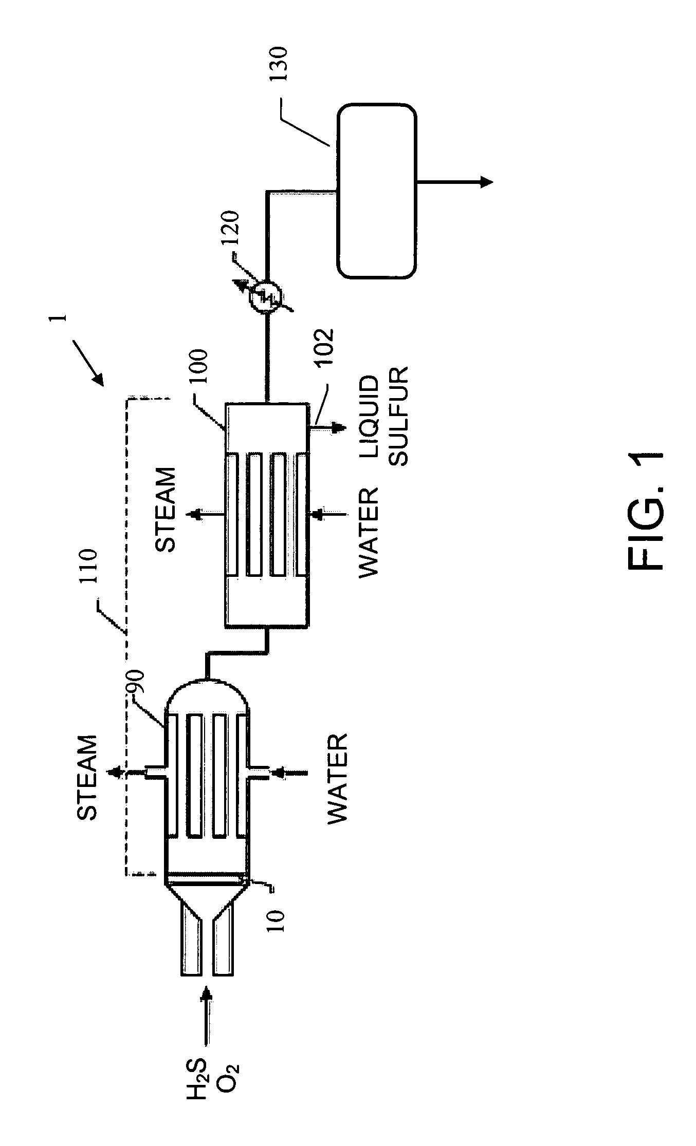
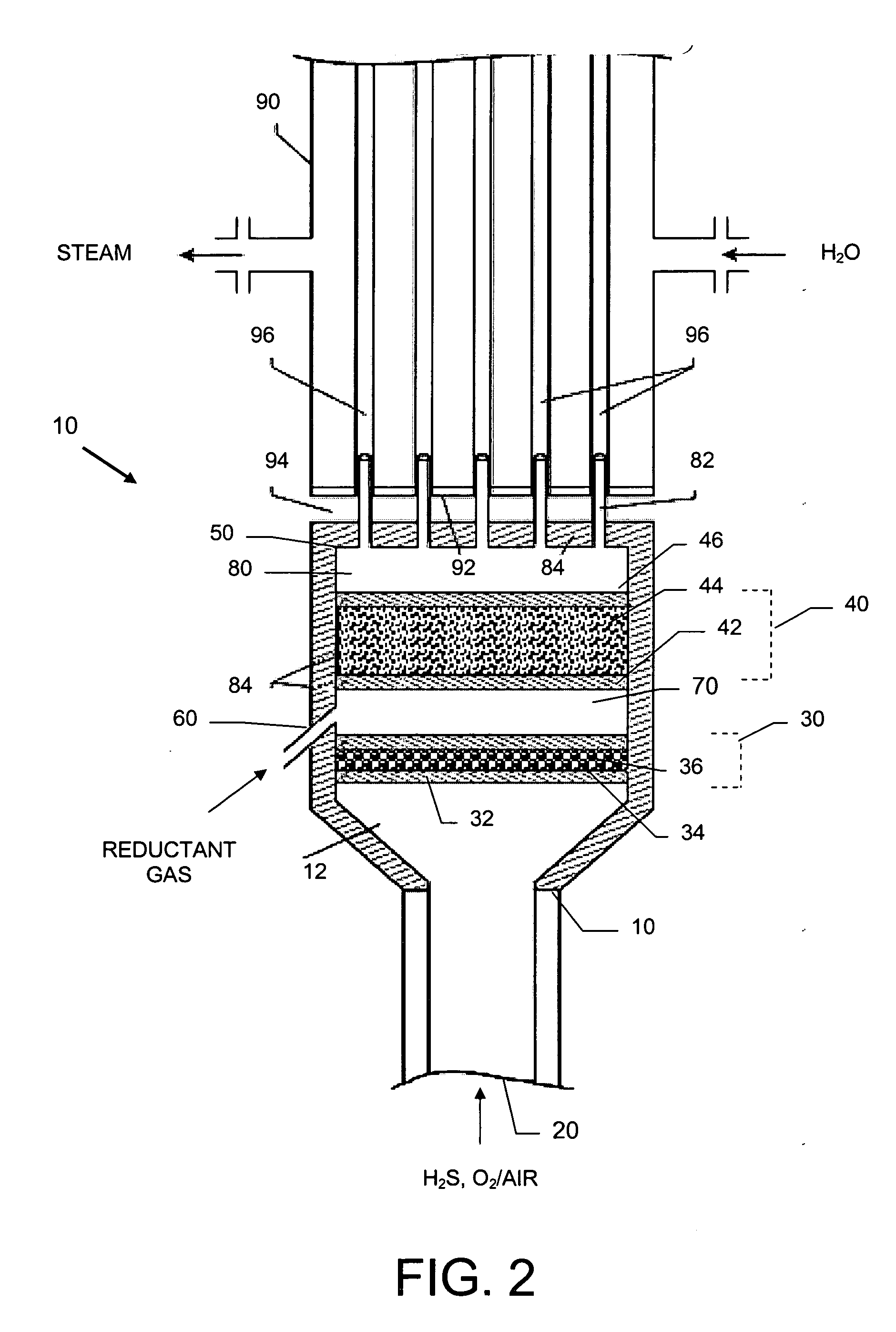
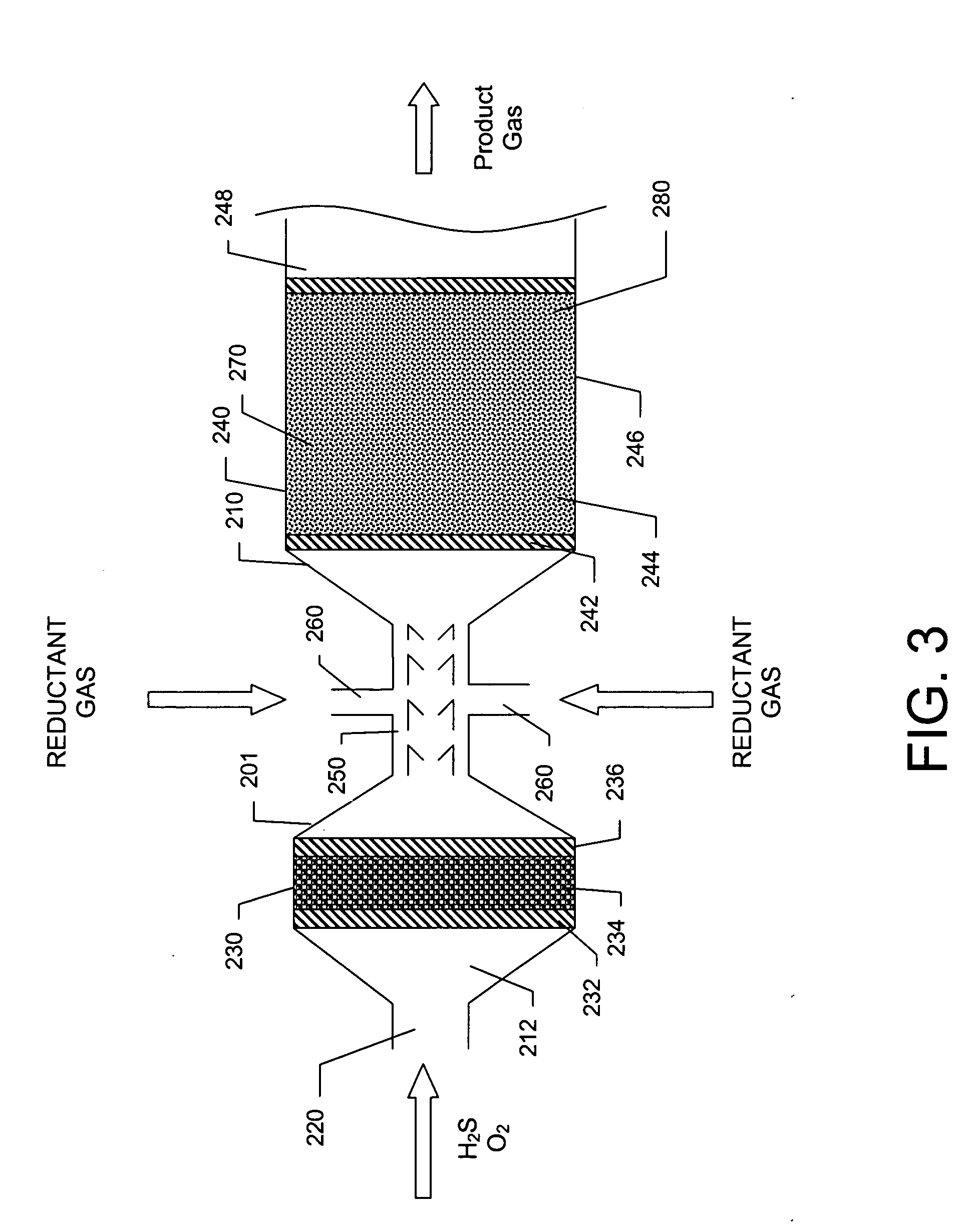
[0044] A basic SPOC-II™ sulfur recovery system 1, shown in FIG. 1, includes reactor 10 and a cooling zone 110, which contains a heat exchanger 90 and a sulfur condenser 100. Depending on the purity of the H2S stream, the particular contaminating gases included in the feedstock, and the purity requirements for the emerging gas stream, the system may also include a heater 120 and one or more tail gas clean up unit 130. The reactor is preferably similar to the short contact time (i.e., 200 milliseconds or less) / fast quench (i.e., less than one second) reactors that are used for carrying out the catalytic partial oxidation of light hydrocarbons and hydrogen sulfide as described in U.S. Pat. No. 6,403,051 or U.S. Pat. No. 6,579,510, except in the present case reactor 10 is modified to include two different reaction zones in serial arrangement. The first reaction zone is suitable for carrying out the catalytic partial oxidization of H2S to gaseous elemental sulfur and water. The second re...


PUM

PropertyMeasurementUnit
temperaturesaaaaaaaaaa
temperatureaaaaaaaaaa

Abstract

Apparatus and process for recovering elemental sulfur from a H2S-containing waste gas stream are disclosed. The apparatus preferably comprises a first reaction zone for carrying out the catalytic partial oxidation of H2S, a second reaction zone for the catalytic partial reduction of any incidental SO2 produced in the first reaction zone, and a cooling zone including a sulfur condenser. According to a preferred embodiment of the process, a mixture of H2S and O2 contacts a catalyst in the first reaction zone very briefly (i.e, less than about 200 milliseconds) producing primarily S0 and H2O. Some SO2 is also present in the first stage product gas mixture. A reductant gas (e.g. CO, or CH4 or natural gas) is fed together with the first stage product gas mixture to a second catalytic reaction zone where the partial reduction of the SO2 component to elemental sulfur and CO2 is carried out.

Description

CROSS REFERENCE TO RELATED APPLICATIONS [0001] This application claims the benefit under 35 U.S.C. § 119(e) of U.S. Provisional Patent Application No. 60 / 536,794 filed Jan. 15, 2004, the disclosure of which is incorporated herein by reference.BACKGROUND OF THE INVENTION [0002] 1. Technical Field of the Invention [0003] The present invention generally relates to sulfur recovery processes and to apparatus for removing sulfur from H2S-containing gas streams and producing elemental sulfur. More particularly, the invention relates to processes that employ an H2S catalytic partial oxidation stage followed by a SO2 catalytic partial reduction stage, and to apparatus for carrying out such processes. [0004] 2. Description of the Related Art [0005] Sulfur removal from H2S-containing gas streams is a field of endeavor that is receiving a great deal of attention today, particularly in the petroleum industry. Considerable quantities of H2S are created from the refining of petroleum in processes ...

Claims


Application Information

Patent Timeline
Patent Type & Authority Applications(United States)
IPC IPC(8): B01D53/34B01D53/86C01B17/02C01B17/04
CPCB01D53/8615C01B17/0413C01B17/0473C01B17/046
Inventor KELLER, ALFRED E.RAMANI, SRIRAM
Owner CONOCOPHILLIPS CO
Why Eureka
Try Eureka