Surface directed cellular attachment

Active Publication Date: 2005-09-08
GEORGIA TECH RES CORP
View PDF99 Cites 58 Cited by
  • Summary
  • Abstract
  • Description
  • Claims
  • Application Information

AI Technical Summary

Benefits of technology

[0015] The present invention describes a biomaterial for implantation into the body. The biomaterial, which can be a hydrogel, possesses a textured surface which is comprised of superficial surface pores. Stated differently, the pores on the surface of the hydrogel substrate do not extend throughout the hydrogel but instead remain within a region near the surface. The hydrogel substrate can be comprised of two or more pore sizes. Specifically, the pores of the first size each have a diameter of between 3 and 1000 micrometers, preferably between 10 and 300 micrometers, and preferably between 30 and 100 micrometers. Further, the pores of the second size would each have a diameter of between 0.5 to 20 micrometers, preferably between 1 to 10 micrometers, and preferably between 2 and 5 micrometers. One embodiment of the present invention provides the second, smaller pores disposed within the first, larger pores. The superficial pores of the present invention extend into the hydrogel substrate less than 1 millimeter, preferably 500 micrometers, and preferably 200 micrometers, from the surface. The hydrogel substrate of the present embodiment can comprise polyvinyl alcohol having a water content of at least 5% and preferably at least 30%.
[0016] The present invention is also drawn to a hydrogel s

Problems solved by technology

One limitation of the prior art is that the hydrogels produced are relatively nonporous and the pore size and degree of porosity, that is the density of the pores within the hydrogel, cannot vary independently of the mechanical properties or stiffness of the hydrogel.
A disadvantage of Yao et al. is that the range of attainable pore sizes is limited.
Moreover, the invention of Yao et al. is limited in that it can only produce hydrogels whose pores extend throughout the hydrogel.
A further disadvantage of Yao et al. is that the pore sizes are broadly distributed about the average pore size.
The disadvantages of the artificial disc devices of the prior art are numerous.
These rigid materials are only minimally compatible with natural, living bone and separation of the implant from the bone is often observed over long-term implantation.
In addition, materials used in artificial discs of the prior art have physical and mechanical properties distinctly different from those of natural spinal, discs and

Method used


Image

  • Surface directed cellular attachment
  • Surface directed cellular attachment
  • Surface directed cellular attachment

Examples


Example

Example 1

[0067] A simple mold surface pattern in accordance with this invention, for example, is an array of cylinders which are 5 μm in diameter and 5 μm in height. To construct a mold surface with this pattern, a 4-inch diameter silicon wafer is coated with a 5 μm thick layer of SU-8 2005 by spin coating at 3000 rpm for about 30 seconds. The wafer is then placed on a hotplate at 65° C. for about 1 minute and then at 95° C. for about 2 minutes. The wafer is then exposed to UV light through a photomask defining the array of cylinders using, for example, a mask aligner (Karl Suss MA-6). The exposure time is calculated to give an exposure energy of 75 mJ / cm2 at a wavelength of 365 nm. The exposed areas of the photoresist are then crosslinked by heating the wager on a hotplate at 65° C. for about 1 minute and then at 95° C. for about 1 minute. The unexposed areas of the photoresist are then dissolved away by immersing the wafer in solvent (SU-8 Developer, MicroChem, Newton, Mass.) for...

Example

Example 2

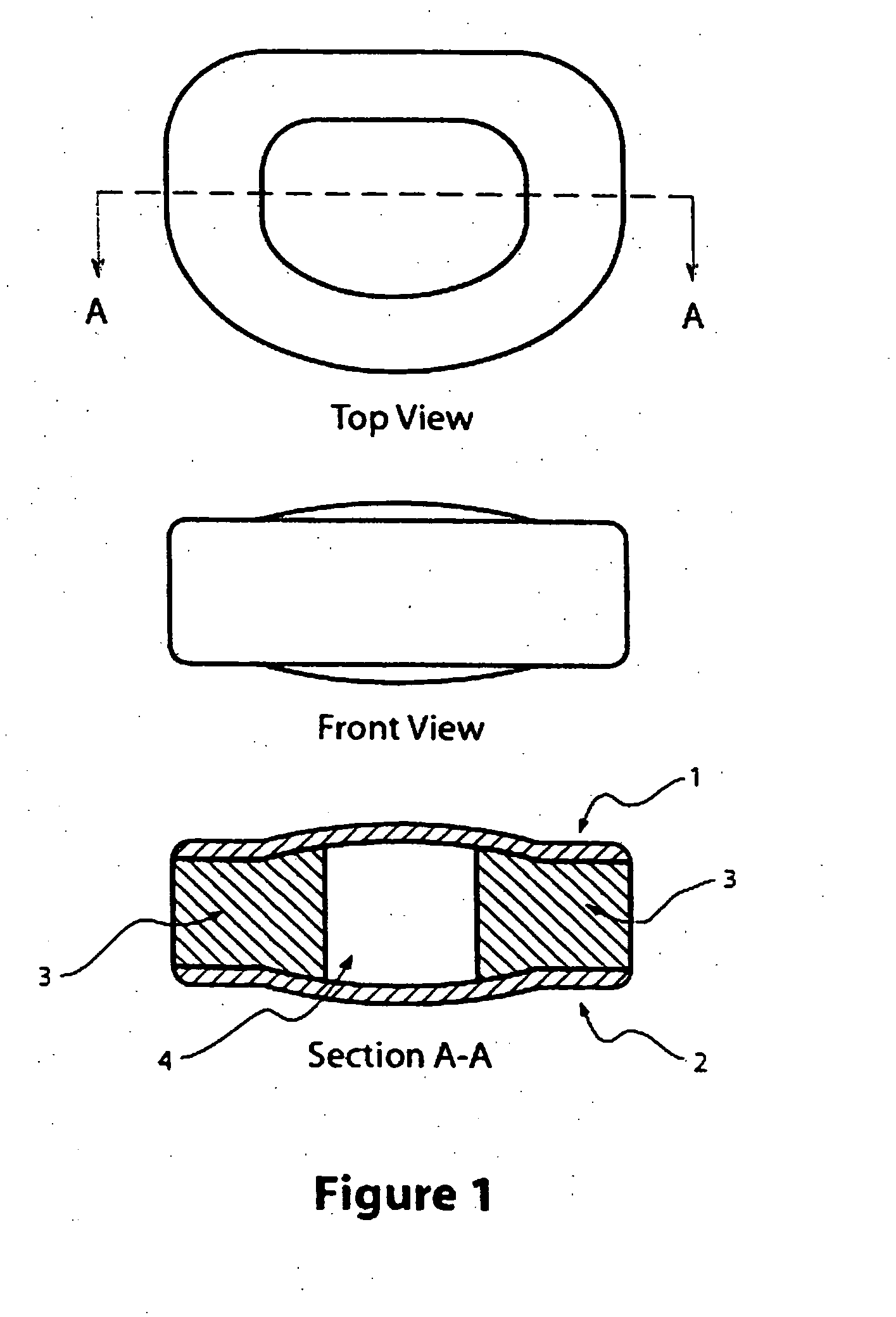
[0068] A more complicated pattern for a hydrogel mold surface, in accordance with the present invention when generated could for example, consist of an array of cylinders 100 μm in diameter and 100 μm in height. Each cylinder is topped with a smaller array of cylinders, 5 μm in diameter, and 5 μm in height. The construction of such a mold requires two layers of photoresist and two separate exposures of those layers. First, a 4-inch diameter silicon wafer is coated with a 100 μm thick layer of SU-8 2050 by spin coating at 1700 rpm for about 30 seconds. The wafer is then placed on a hotplate at 65° C. for about 4 minutes and then at 95° C. for about 1 minute. The wafer is then exposed to UV light through the photomask defining the array of large cylinders, using, for example, a mask aligner (Karl Suss MA-6). The exposure time is calculated to give an exposure energy of 450 mJ / cm2 at a wavelength of 365 nm.

[0069] The exposed areas of the photoresist are then cross-linked by ...

Example

Example 3

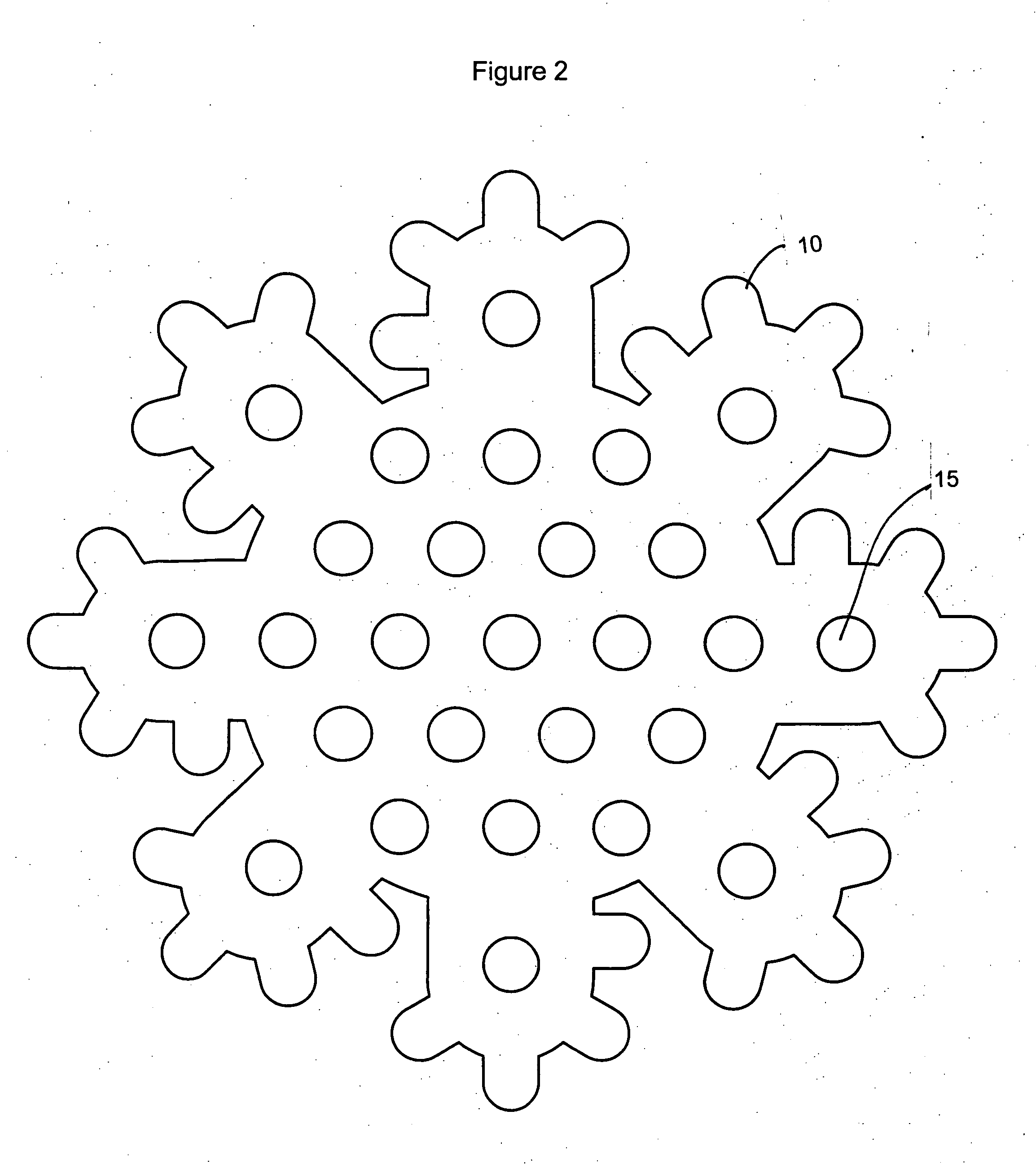
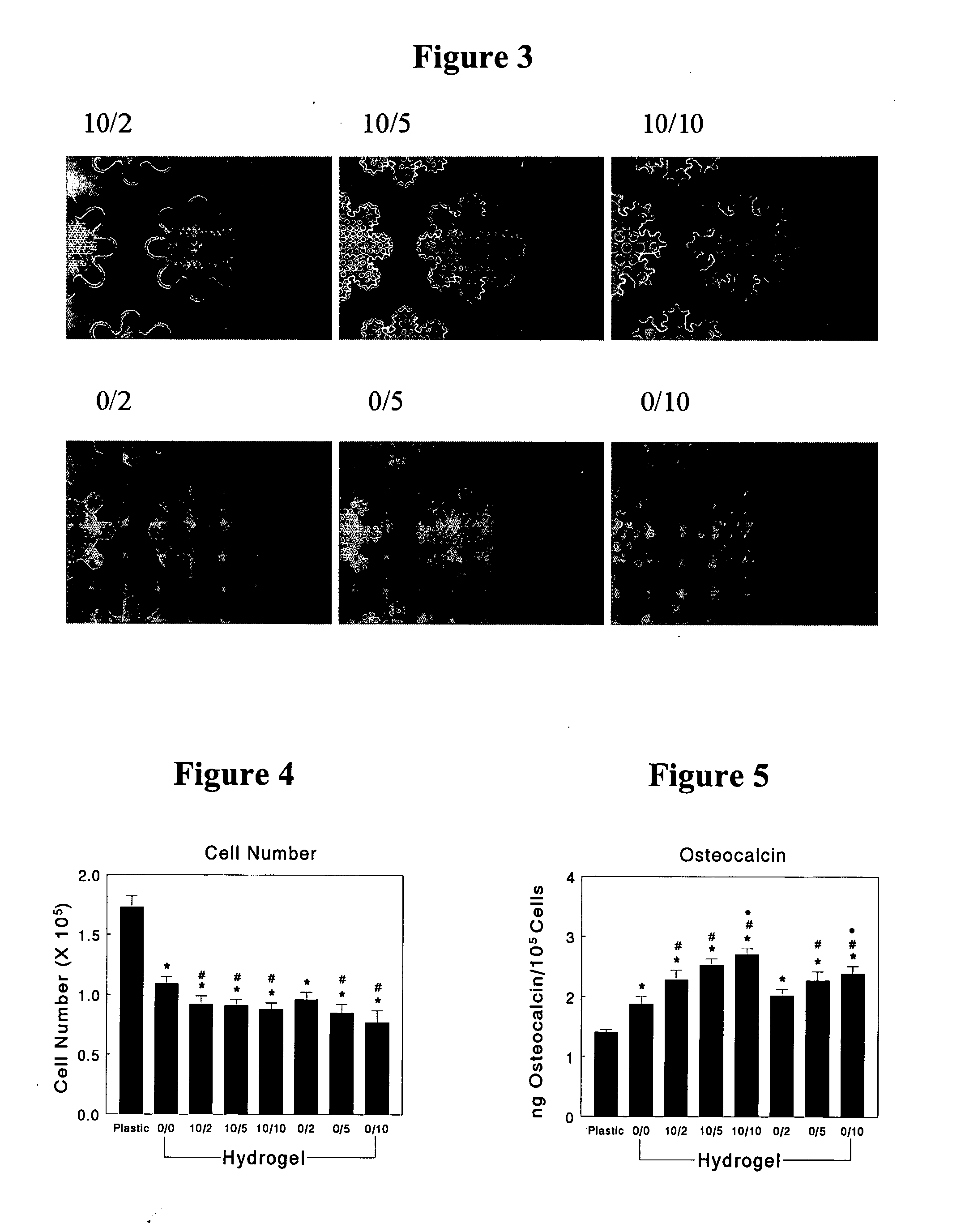
[0070] Under the methods of this invention, enhanced differentiation of cells into bone or bone-like cells is seen. Specifically, experiments were run using the PVA-H of this invention in multiple forms. This description references FIGS. 3-5 for clarity. As shown in FIG. 3 there were seven conformations of the surface topography taught by this invention used in this experiment—one being smooth hydrogel. Specifically, conformation is described using a two number nomenclature system such as PVA-H 10 / 2. PVA-H 10 / 2 refers first to the size of the large pore on the surface. As described above, the large pore can exist in a complex structure resembling a snowflake. The number 10 in the first position represents a large pore of 100 μm in diameter. The number in the second position of the nomenclature system refers to the size and arrangement of the small pores superimposed on the large pore surface. The second position numbers of 2, 5, and 10 refer to a diameter of 2 μm, 5 μm, an...


PUM

PropertyMeasurementUnit
Lengthaaaaaaaaaa
Lengthaaaaaaaaaa
Lengthaaaaaaaaaa

Abstract

Implantable biomaterials, particularly hydrogel substrates with porous surfaces, and methods for enhancing the compatibility of biomaterials with living tissue, and for causing physical attachment between biomaterials and living tissues are provided. Also provided are implants suitable for load-bearing surfaces in hard tissue repair, replacement, or augmentation, and to methods of their use. One embodiment of the invention relates to an implantable spinal disc prosthesis.

Description

CROSS REFERENCE TO RELATED APPLICATIONS [0001] The present invention claims the priority benefit of U.S. Provisional Patent Application Ser. No. 60 / 542,514 filed Feb. 6, 2004, the entire contents of which are hereby incorporated by reference.BACKGROUND OF THE INVENTION [0002] 1. Field of the Invention [0003] The present invention relates to the use of surface modified biocompatible materials to promote the attachment of bone or bone-like cells to an implant surface. The surface of the biomaterials, which may include hydrogels, when modified in accordance with the description herein, directs the cells that migrate to the implant site to differentiate into cells that attach and lay down bone or bone-derivative material, or cartilage or cartilaginous material further enhancing the biocompatibility of the implanted device. [0004] 2. Background Art [0005] Materials used in the construction of implantable medical devices must be nontoxic, nonantigenic, and noninflammatory. Hydrogels are a...

Claims


Application Information

Patent Timeline
IPC IPC(8): A61K9/14
CPCA61L27/16A61L27/52Y10S514/944A61L27/56C08L29/04B33Y80/00A61P19/00
Inventor BOYAN, BARBARA D.KENNEDY, STEPHEN J.
Owner GEORGIA TECH RES CORP
Why Eureka
Try Eureka