Electrochemical sensor and method for continuous analyte monitoring

Inactive Publication Date: 2005-09-29
ROCHE DIABETES CARE INC
View PDF32 Cites 126 Cited by
  • Summary
  • Abstract
  • Description
  • Claims
  • Application Information

AI Technical Summary

Benefits of technology

[0009] In one embodiment of the invention the retention volume is defined or enclosed, at least in part, by an analyte-permeable membrane and the ratio of the retention volume to the surface area of the semipermeable membrane defining that volume, at least in part, is less than 2 mm, more preferably less than 1 mm. The low volume to surface area ratios are preferred in that they improve the rate of diffusional equilibrium between the fluid being tested and the retention volume medium, and thereby it works to minimize the refractory period (the recovery period) of the sensor.
[0010] In one preferred embodiment the enzyme component is selected so that it is substan

Problems solved by technology

There are unique problems presented by the design and construction of biological sensors capable of repeated use in vitro and/or continuous use in vivo.
Indeed, inherent in such functional r

Method used


Image

  • Electrochemical sensor and method for continuous analyte monitoring
  • Electrochemical sensor and method for continuous analyte monitoring
  • Electrochemical sensor and method for continuous analyte monitoring

Examples


Example

EXAMPLE 1

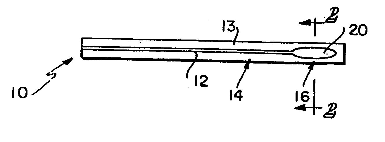
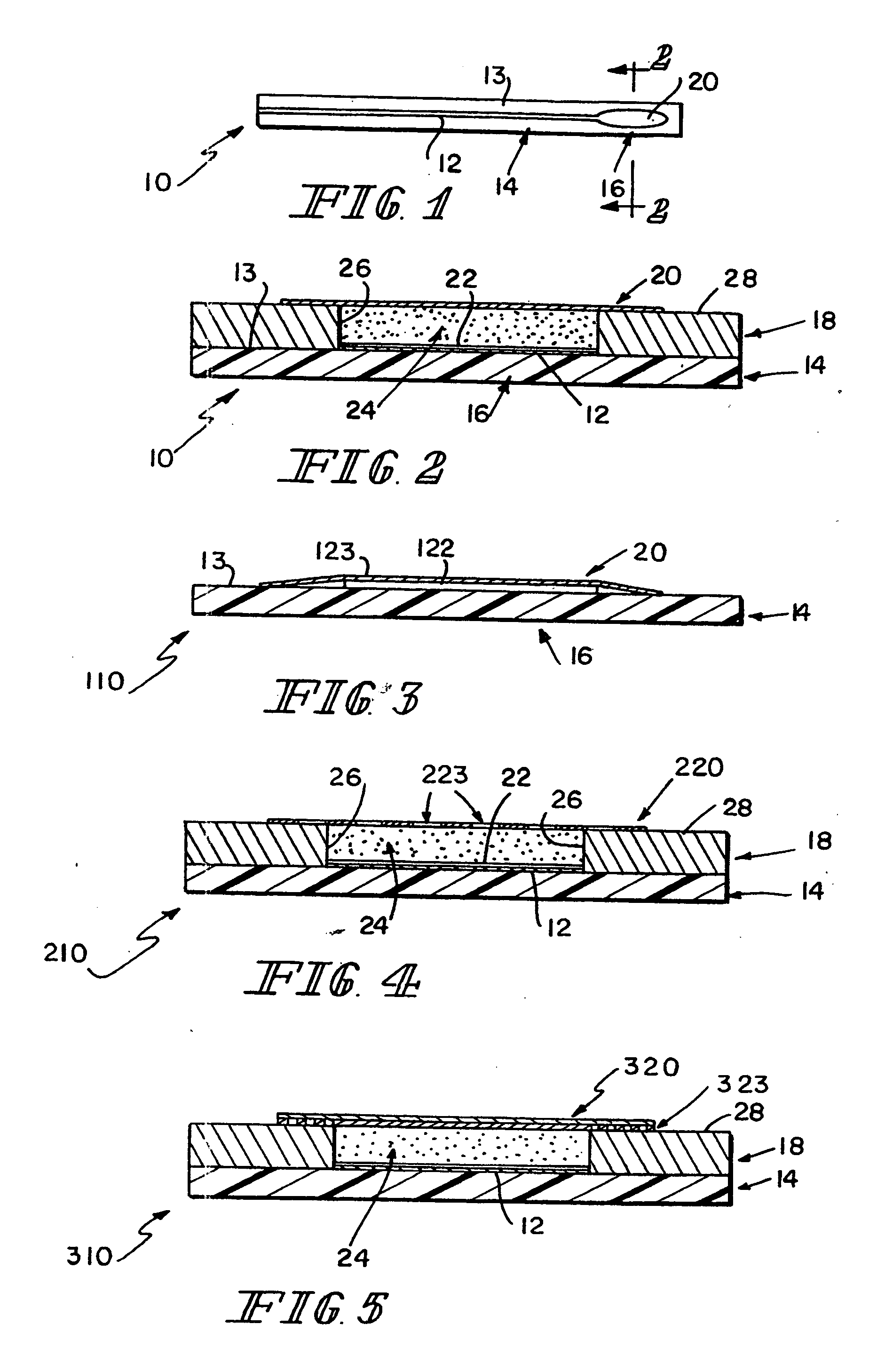
[0052] A sensor in accordance with the present invention is formed similarly to sensor 10 of FIGS. 1-2, except that it does not include membrane 20. The enzyme and electron mediator is entrapped in a polymer matrix on the electrode. This polymer matrix was prepared by electropolymerization of pyrrole and pyrrole-mediator derivatives. This method entrapped the enzyme in a polymer matrix on the electrode, and, by incorporating mediator-derivatized pyrrole into the polymer, provided for an immobilized mediator for transfer of electrons within the sensor.

[0053] Platinum disc electrodes were suitable for preparing sensors in accordance with this method. A mediator which was suitable for copolymerization in a matrix was be prepared by the following reaction sequence:

Synthesis of Pyrrole-Modified Osmium (Bisbipyridyl) Pyridinium Chloride

[0054] Pyrrole-modified Osmium (bisbipyridyl) pyridinium Chloride was prepared by the following reaction sequence:

Cleaning Procedure for ...

Example

EXAMPLE 2

[0071] A sensor 410 consists of conductors 12, 15 and reagents deposited on a flat polymeric substrate 14. Materials for encapsulation of the conductors 12, 15 are provided, and reagents that form a semipermeable biocompatible layer over the reagent-containing sensing area 16. See FIG. 10.

Processes and Materials:

[0072] Substrate: Polyimid (such as Kapton® polyimide film, which is commercially available from E.I. DuPont de Nemours, Wilmington, Del., and Upilex® polimide film which is commercially available from UBE Industries Ltd, Japan) 0.005″ (0.127 mm) thick with gold electrodes and conducting tracks.

[0073] Processing: Material is washed with water, acetone, and methylene chloride, then dried at 180° C. for 20 hours. Material is placed in a vacuum chamber and metalized with 50 Å Chromium followed by 500 Å Gold. Metalized material is removed. A laminated photoresist is applied. The resist is exposed, and developed in an aqueous salt solution. Then the metal pattern is...


PUM

PropertyMeasurementUnit
Concentrationaaaaaaaaaa
Volumeaaaaaaaaaa
Currentaaaaaaaaaa

Abstract

Sensors and a method for detecting an analyte are described. Sensors each have a volume of a hydrophilic medium that retains an amount of analyte proportionate to the concentration of analyte in a biological fluid, electrodes and a redox enzyme in contact with medium, and an electron transfer mediator. The fluid contacts sensors and at initially predetermined intervals intermittently applies a potential to electrode sufficient to oxidize the mediator and sensing current through electrode as a function of the duration of the applied potential. The applied mediator oxidizing applied potential is maintained for a period of time sufficient to determine the rate of change of current with time through electrode. The current flow is correlated with the current flow for known concentrations of the analyte in medium.

Description

CROSS-REFERENCE TO RELATED APPLICATIONS [0001] This application is a continuation of U.S. application Ser. No. 10 / 069,308 filed Feb. 20, 2002, which claims priority to PCT / US00 / 25631 filed Sep. 19, 2000, which claims priority to U.S. Provisional Application No. 60 / 154,731 filed Sep. 20, 1999.FIELD OF THE INVENTION [0002] This invention relates to sensors for detecting the presence or quantity of an analyte in a biological fluid. More particularly, this invention is directed to a sensor adapted particularly for indwelling or implanted use. Analyte concentrations are measured electrochemically in a contained detection retention volume of an analyte-permeable medium separated from the biological fluid with a semi-permeable membrane. BACKGROUND AND SUMMARY OF THE INVENTION [0003] There has been a significant research and development effort directed to the development of electrochemical sensors capable of detecting the presence and / or quantity of biologically significant analytes. Many, ...

Claims


Application Information

Patent Timeline
IPC IPC(8): A61B5/00C12Q1/00G01N27/26
CPCA61B5/14532A61B5/1486C12Q1/006C12Q1/004C12Q1/001
Inventor BUCK, HARVEY B.ESSENPREIS, MATTHIAS
Owner ROCHE DIABETES CARE INC
Why Eureka
Try Eureka