Catheter tracking with phase information

a technology of phase information and catheter, applied in the direction of catheter, magnetic variable regulation, sensors, etc., can solve the problems of 3-6% of complex, direct visualization critical, and relatively high complication rate, and achieve the effect of reliable tracking of the position of the catheter

Active Publication Date: 2005-11-03
SUNNYBROOK HEALTH SCI CENT +1
View PDF6 Cites 106 Cited by
  • Summary
  • Abstract
  • Description
  • Claims
  • Application Information

AI Technical Summary

Benefits of technology

[0027] A second object of the present invention is to provide a phase sensitivity method for reliably tracking the position of catheters using low-resolution clinically acceptable MRI scans that enable real-time interventional MRI applications.
[0028] A third object of this invention is to provide a phase sensitivity method which enables real-time MRI tracking of the position of endovascular access devices and interventional probes, including surgical tools and tissue manipulators, devices for in vivo delivery of drugs, angioplasty devices, biopsy and sampling devices, devices for delivery of RF, thermal, microwave or laser energy or ionizing radiation, and internal illumination and imaging devices, such as catheters, endoscopes, laparoscopes, and related instruments.
[0031] According to the invention, phase information can track the position of a catheter or other interventional device more accurately than magnitude sensitivity information because the receive phase sensitivity of a microcoil is unique for any given position and orientation of the microcoil, and phase information is more spatially varying than magnitude projections. In the method of the invention, both the position and orientation of a microcoil can be determined using phase information. Catheter tip tracking is carried out by obtaining two phase images; one integrated phase image projected onto the axial plane and one in an oblique plane through the center of the coil and normal to the microcoil plane. In another preferred embodiment of the invention, phase information adequate for MRI localization can also be obtained from only one plane, for example, a plane through the microcoil perpendicular to the axial plane, wherein such phase information is used together with position information obtained from projections, or based on a locator that produces substantial phase patterns. Furthermore, the phase images obtained for catheter tracking using the method of the present invention can be low-resolution MR images, wherein clinically useful MRI scans can be obtained relatively rapidly thereby making catheter tracking using phase information clinically useful for real-time interventional MRI applications.

Problems solved by technology

However, 3-6% of these are complicated by aortic or atrial perforations due to incorrect needle positioning.
This relatively high complication rate can in part be attributed to the inability to directly visualize critical endocardial landmarks using a two-dimensional projection x-ray fluoroscopy.
Conventional X-ray guided interventions suffer from a number of limitations, including: (1) limited anatomical visualization of the body and blood vessels during the examination, (2) limited ability to obtain a cross-sectional view of the target tissue or blood vessel, (3) inability to characterize important pathologic features of atherosclerotic plaques, (4) limited ability to obtain functional information on the state of the related organ, and (5) exposure of the subject to potentially damaging x-ray radiation.
Despite the several distinct advantages MRI has over x-ray fluoroscopy, MRI guided positioning of catheters and other devices has numerous challenges related to imaging artifacts, electromagnetic interference, and the necessity for cardiac and respiratory gating and rapid imaging and display.
However, these patents do not provide for artifact-free MR visibility in the presence of rapidly alternating magnetic fields, such as would be produced during echo-planar MR imaging pulse sequences used in real-time MR guidance of intracranial drug delivery procedures.
Nor do these patents teach a method for monitoring with MR-visible catheters the outcomes of therapeutic interventions, such as, for example, drug delivery into brain tissues or cerebral ventricles.
Image distortion may include general signal loss, regional signal loss, general signal enhancement, regional signal enhancement, and increased background noise.
The magnetic susceptibility artifact produced by the device should be small enough not to obscure surrounding anatomy, or mask low-threshold physiological events that have an MR signature, and thereby compromise the physician's ability to perform the intervention.
However, an additional limitation with passive tracking is that quantitative information about the catheter position or orientation is not obtained.
This inhibits automatic scan plane prescription and the catheter must be manually kept within the scan plane.
However, in common with other currently used endovascular access devices, such as catheters, microcatheters, and guidewires, the catheter tip is difficult to see on MRI because of inadequate contrast with respect to surrounding tissues and structures.
This makes accurate localization difficult and degrades the quality of the diagnostic information obtained from the image.
Also, the mere observation of the location of the catheter in the drug delivery system does not reliably or consistently identify the position, movement and / or efficient delivery of drugs provided through the system.
At the same time, the eddy currents are limited due to the ultra-thin conductor coating on the device.
There is, however, a weakness with this approach in that the peaks of the projections do not necessarily correspond to the center of the micro-coil.
This makes peak finding through curve fitting difficult.
The method is also inherently susceptible to noise; high-resolution scans are needed; and it is not possible to obtain orientation information from the magnitude projections of a single coil [10].
However, the application of this technology to MRI is problematic due to the simultaneous use of RF signals by the MR scanning.
Potential difficulties are the heating of the receiving antenna in the device by the high amplitude excitation RF transmissions of the MRI scanner and artifacts in the MR image.
However, this method cannot directly determine the orientation of the device, may be subject to heating of the coil, and requires time to implement that reduces the temporal resolution available for repeated MRI acquisitions.
Although the patented inventions referenced above provide useful technological advances in the field of image-guided interventions, each invention also has significant inherent limitations.
The prior art methods are also inherently susceptible to noise; high-resolution scans are needed; and it is not possible to obtain orientation information from the magnitude projections of a single coil [10].

Method used


Image

  • Catheter tracking with phase information
  • Catheter tracking with phase information
  • Catheter tracking with phase information

Examples


Embodiment Construction

Definitions:

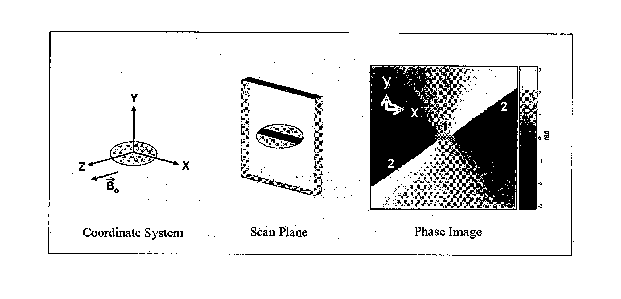
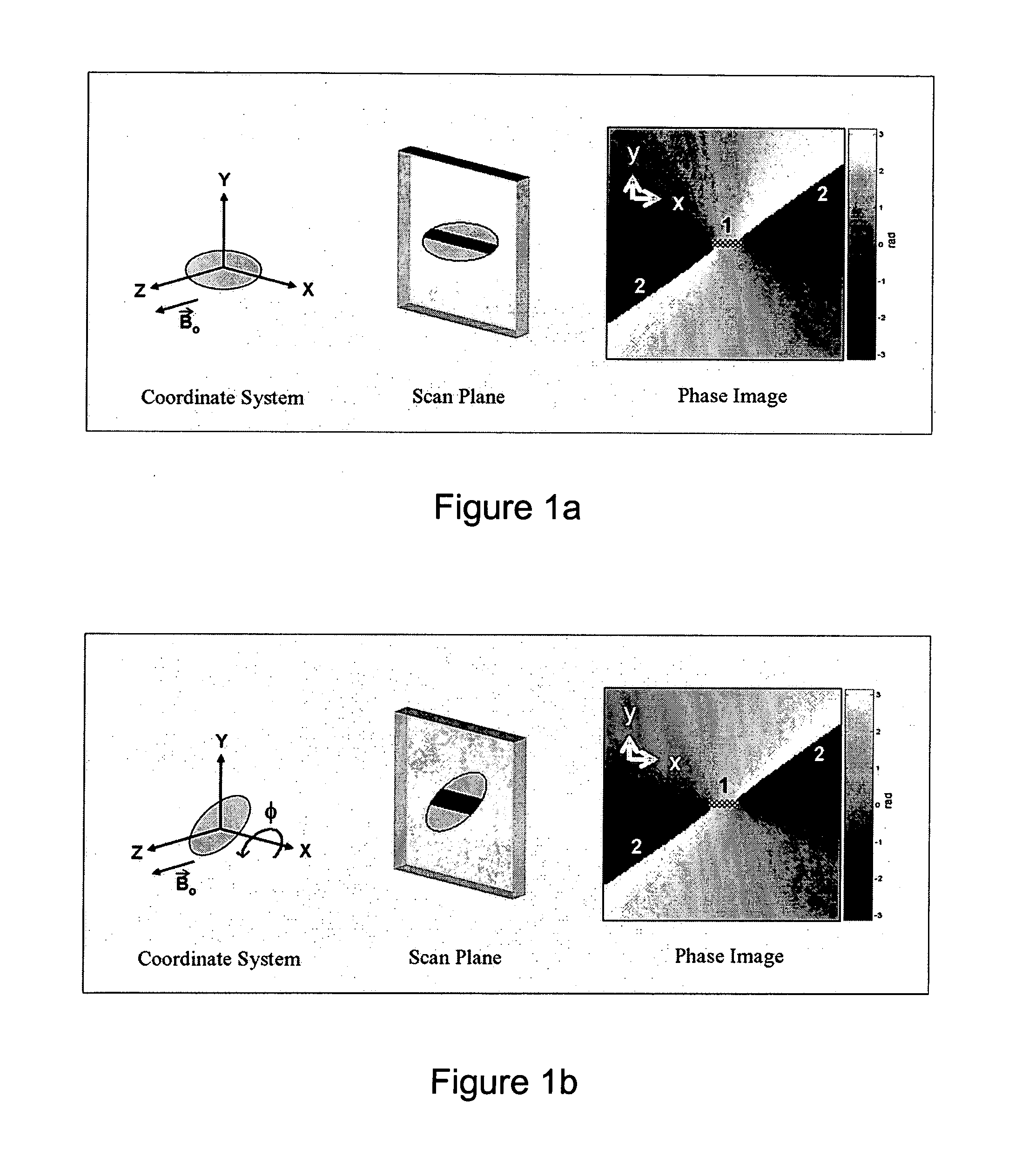
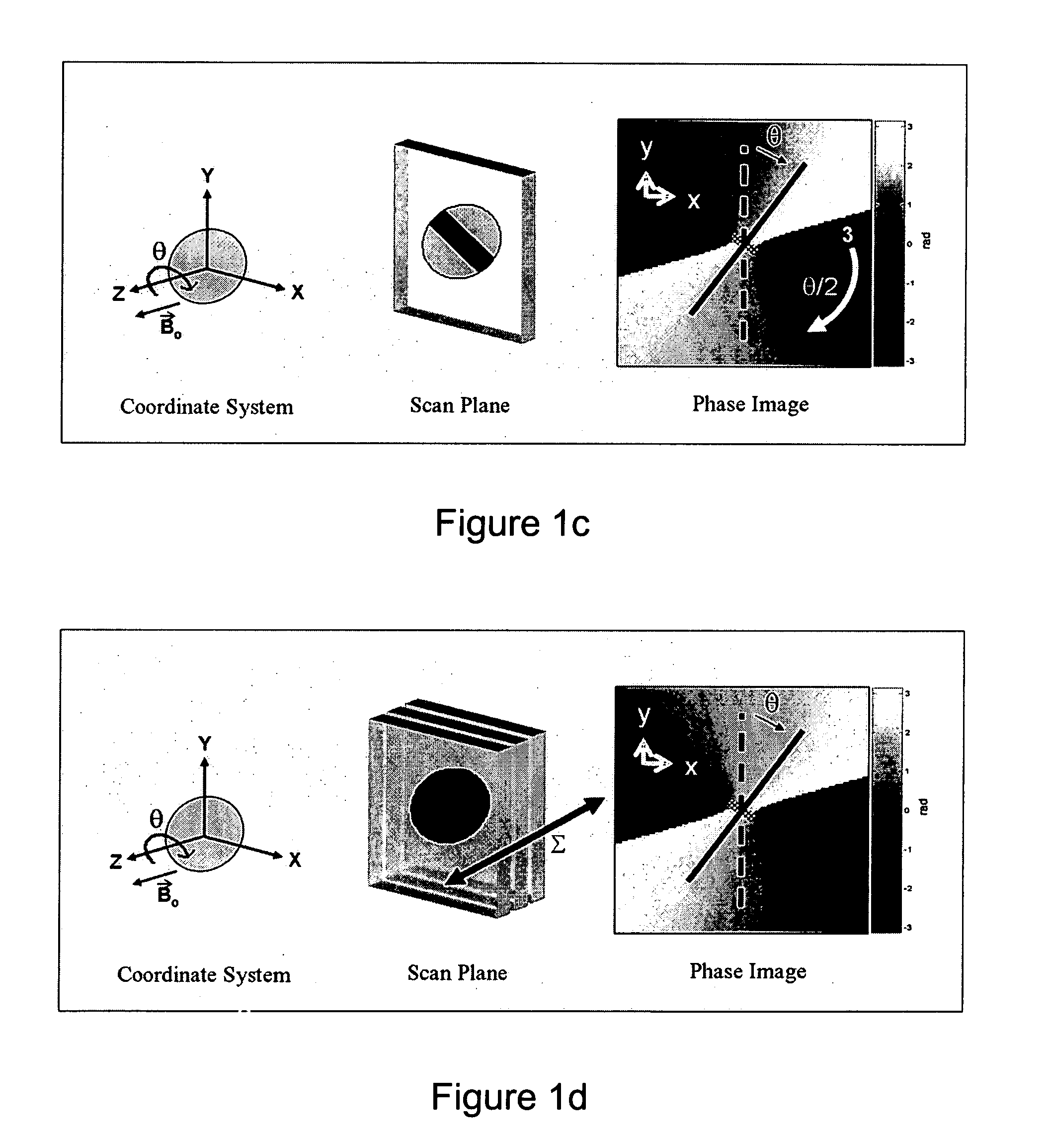
[0077] As used herein the phrase “phase pattern” refers to a spatial map of phase in the MR signal in a particular plane of interest.

[0078] As used herein the phrase “catheter tracking” refers to the act of determining information about the position and / or orientation of a catheter tip.

[0079] As used herein the phrase “marker for perturbing the phase of the magnetic resonance signal” means using a receive coil of arbitrary shape used to introduce phase into the MR signal through its receive sensitivity field or using a material of arbitrary shape and sufficient magnetic susceptibility to perturb the static magnetic field in the volume surrounding the material.

[0080] As used herein the phrase “microcoil” refers to small tuned radiofrequency antenna used to receive MR signal or transmit an MR excitation field.

[0081] As used herein the phrase “field map” refers to a spatial map of the static magnetic field in a plane of interest.

[0082] Active MRI tracking of catheter...


PUM


Abstract

The present invention discloses a method for determining the position and / or orientation of a catheter or other interventional access device or surgical probe using phase patterns in a magnetic resonance (MR) signal. In the method of the invention, global two-dimensional correlations are used to identify the phase pattern and orientation of individual microcoils, which is unique for each microcoil's position and orientation. In a preferred embodiment of the invention, tracking of interventional devices is performed by one integrated phase image projected onto the axial plane and a second image in an oblique plane through the center of the coil and normal to the coil plane. In another preferred embodiment, the position and orientation of a catheter tip can be reliably tracked using low resolution MR scans clinically useful for real-time interventional MRI applications. In a further preferred embodiment, the invention provides real-time computer control to track the position of endovascular access devices and interventional treatment systems, including surgical tools and tissue manipulators, devices for in vivo delivery of drugs, angioplasty devices, biopsy and sampling devices, devices for delivery of RF, thermal, microwave or laser energy or ionizing radiation, and internal illumination and imaging devices, such as catheters, endoscopes, laparoscopes, and related instruments.

Description

CROSS REFERENCE TO RELATED U.S PATENT APPLICATIONS [0001] This patent application relates to U.S. provisional patent application Ser. No. 60 / 565,845 filed on Apr. 28, 2004 entitled CATHETER TRACKING WITH PHASE INFORMATION.FIELD OF THE INVENTION [0002] The present invention relates to a method for determining the position and / or orientation of a catheter or other interventional access device or surgical probe using phase patterns in a magnetic resonance (MR) signal. BACKGROUND OF THE INVENTION [0003] Catheters and other endovascular access tools have long been used in the art as medical devices to advance therapeutic agents to an anatomic point of interest for examination, diagnosis, and intervention. Accurate positioning of such interventional devices requires monitoring to ensure that the device is being advanced through the correct structures without causing injury, failing mechanically, and for other reasons known to one skilled in the art. [0004] Methods existing in the art for ...

Claims


Application Information

Patent Timeline
Patent Type & Authority Applications(United States)
IPC IPC(8): A61B5/05A61B5/055A61B5/06A61M25/095G01R33/28
CPCA61B5/06G01R33/287A61B2019/5251A61B2034/2051
Inventor ANDERSON, KEVAN J.T.WRIGHT, GRAHAM A.
Owner SUNNYBROOK HEALTH SCI CENT
Why Eureka
Try Eureka