Gun barrel and method of forming

a technology of gun barrels and tubes, applied in the direction of barrels, weapon components, weapons, etc., can solve the problems of limited the lifetime of conventional steel gun barrels to unacceptably short times, increased wear of the inner surface of the gun barrel, and barrel failure, etc., to achieve high strength, high strength overwrap, and high strength. the effect of high strength

Inactive Publication Date: 2005-12-08
ATS MER LLC
View PDF18 Cites 30 Cited by
  • Summary
  • Abstract
  • Description
  • Claims
  • Application Information

AI Technical Summary

Benefits of technology

[0010] The present invention provides novel high temperature and wear resistant ceramic matrix composite (CMC) gun barrel liners for gun barrels having a lightweight outer shell consisting of a metal matrix composite (MMC) or a high strength metal such as titanium. In the case of the CMC inner layer, the unique use of a mandrel with inverse rifling allows for the in-situ generation of rifling in the CMC layer. More particularly, the present invention in one aspect provides a CMC lined gun barrel with no distinct interface between the so-called liner and outer wrap. The fabrication of a CMC lined gun barrel in accordance with the first aspect of the invention entails essentially building the barrel from the inside to the outside, where a male mandrel with the lands and grooves that make up the rifling are machined into the mandrel surface. Uniaxial aligned fibers are then wound into the grooves followed by a variety of winding schemes for each layer of fibers that comprise the liner. For example, combinations of longitudinal, hoop, and angled wraps can be utilized in conjunction with the incremental densification of these layers using liquid preceramic polymers or chemical vapor infiltration. The mandrel is then removed by mechanical or chemical operation.
[0011] In another aspect the present invention provides novel refractory metal or metal alloy lined gun barrels, and methods for forming same and for assembling them into a barrel structure. In this latter aspect, the refractory metal or metal alloy liner can be formed by two different methods. One method involves machining a refractory metal or metal alloy rod or tube to the dimensions of the inner bore and including rifling. The other method involves forming the refractory alloy by plasma transferred arc solid free form fabrication (PTA SFFF). In PTA SFFF, metal powder(s) or a mixture of a metal powder or powders plus a ceramic powder or powders, is fed through a plasma transfer arc welding torch and deposited on the inner surface of a tubular metallic substrate. The position of the torch head is controlled by a multi-axis motion controller, such as a multi-axis CNC controller or a multi-axis robotic controller. The motion of the torch head is controlled so as to deposit 3-dimensional structures of the metal or metal-ceramic mixture on the inner surface of the tubular substrate. Alternatively, a wire feed can be used in place of the powder feed to deposit the desired material. In either case, there is no abrupt interface between the liner and the overwrap, which since it is deposited in the liquid state, will react with the liner to chemically bond the two components. Thus, one innovation of the present invention is the 2 fabrication of a graded gun barrel, which gradually changes from a highly wear resistant bore to a high strength overwrap.

Problems solved by technology

It is well known that the wear of gun barrel inner surfaces has been exacerbated by the use of propellants with extremely high flame temperatures or in the case where very high energy projectiles are fired in rapid and long burst cycles.
This has significantly limited the lifetime of conventional steel gun barrels to unacceptably short times, such that it is widely recognized that higher performance gun barrels are needed.
The cracked and porous chromium layer permits corrosive propellant gases to attack the underlying steel causing what is termed heat checking which causes the barrel to fail by wear, erosion, corrosion, and excessive fatigue of the steel.
However, such coatings have an abrupt interface, and are prone to spalling of the protective coating and are inherently brittle due to the physical properties of the deposited refractory metals.
Another limitation to current small caliber steel gun barrels is that they are heavy and cumbersome to carry.
For small caliber barrels in particular, it is extremely difficult to produce rifling in ceramic liners.
In addition, such machining tends to fracture the fibers which in turn significantly degrades the mechanical properties.

Method used


Image

  • Gun barrel and method of forming
  • Gun barrel and method of forming
  • Gun barrel and method of forming

Examples


example 1

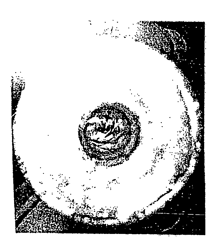
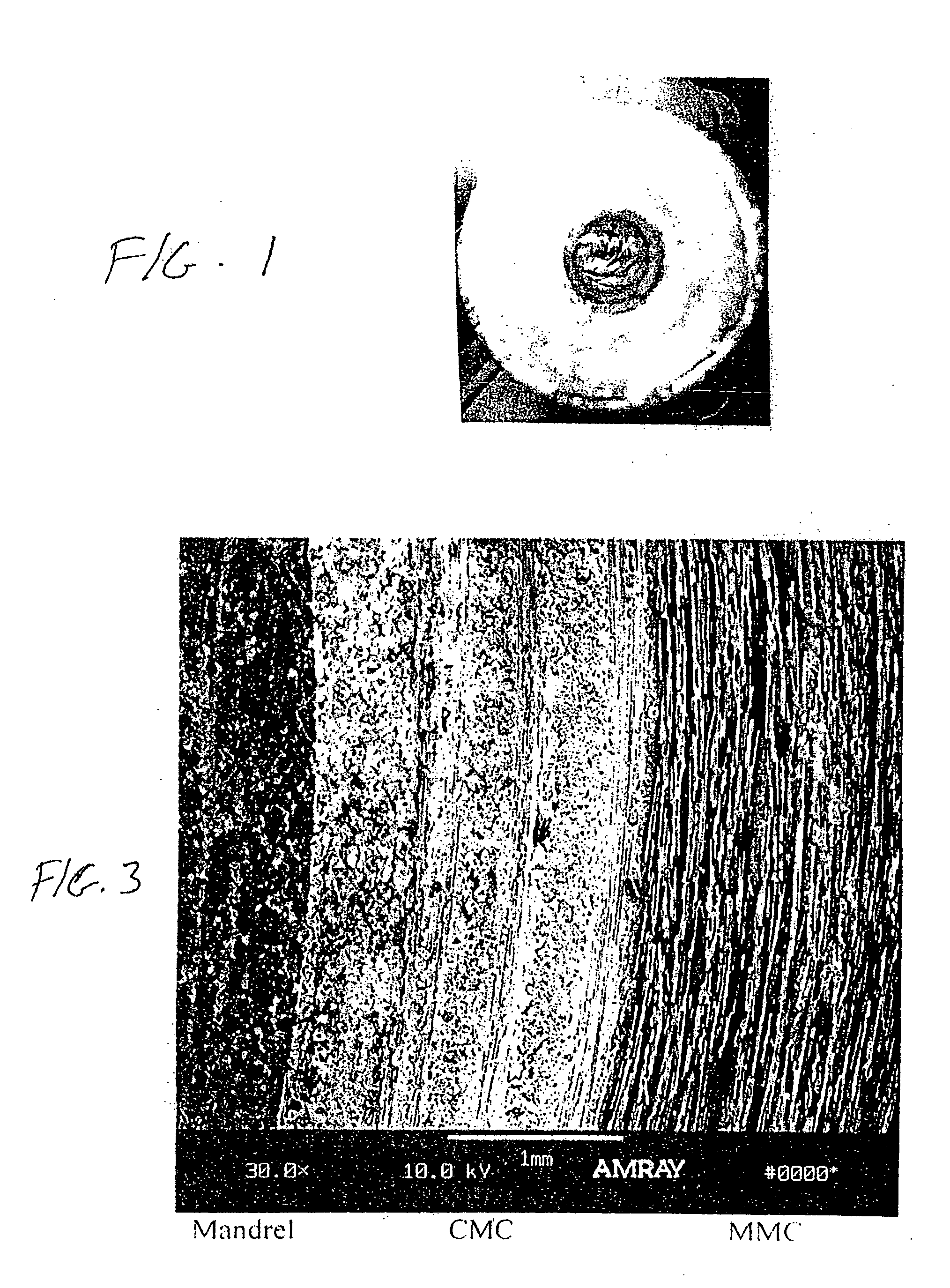
[0030] A graphite mandrel was machined with lands and grooves which replicate the rifling in a barrel. A silicon carbide (SiC) fiber (HI-NICALON available from COI Ceramics, Inc, San Diego, Calif.) was wound into the grooves of the graphite mandrel which was then overwrapped with a hoop layer of the SiC fiber. A SiC preceramic polymer (VL20 available from Kion Corporation, Huntington Valley, Pa.) was infiltrated into the SiC fiber wrappings and pyrolyzed to produce a SiC matrix. The preceramic polymer was reinfiltrated and pyrolyzed in five additional cycles to build up a dense SiC matrix.

[0031] Longitudinal SiC fibers (HI-NICALON available from CIO Ceramics, Inc.) were then wrapped around the SiC / SiC composite layer which was then followed by a hoop wrap and then ±22° wraps. A SiC preceramic polymer (VL20 available from Kion Corporation) was then reinfiltrated and pyrolyzed in five more cycles. Any number of fiber wrap layers in different architectures can be applied, and the SiC ...

example 2

[0034] The graphite mandrel is prepared as in Example 1, and after the initial SiC fiber winding, instead of using a preceramic polymer to form the SiC matrix, the SiC matrix is produced by chemical vapor infiltration (CVI) processing, by subjecting the graphite mandrel to CVI using methyltrichlorosilane and hydrogen in a CVI chamber heated to 1000° C. which produces a SiC matrix in the SiC fiber array. Additional layers of SiC fibers are then wound, and the SiC matrix produced either by CVI or the preceramic polymer. The MMC and final barrel preparation are performed by overwrapping with alumina, and squeeze casting as described in Example 1.

example 3

[0035] A steel tube mandrel was rotated with water flowing in its center, and a plasma transferred arc (PTA) system was used to deposit Ta-50Cr (% by weight) in a molten state on the outer surface of steel tube mandrel and built up layer by layer until the deposited thickness was 0.08″. The Ta-50Cr was produced by feeding equal amounts of Ta and Cr powder to the arc pool. Following deposit of the Ta—Cr layer on the mandrel, a layer of about 0.040″ thickness of pure tantalum was applied with a PTA system which was graded into pure titanium using a programmed computer controlled powder feed system to the PTA arc pool. This operation was carried out in an inert gas chamber with a continuous flow of Ar gas so as to maintain the oxygen content in the chamber at <100 ppm. In this manner a titanium structure was built up for the barrel. The pure Ta layer was produced to avoid any brittle intermetallic formation with the titanium.

[0036] After building the titanium layer, the steel mandrel ...


PUM

PropertyMeasurementUnit
pressuresaaaaaaaaaa
strength heataaaaaaaaaa
strengthaaaaaaaaaa

Abstract

A fabrication technique is described for producing lighter weight and improved wear and erosion resistant gun barrels. The barrels are produced in an unconventional manner from the inside bore to the outside diameter of the barrel and combine a refractory metal, metal alloy, or ceramic composite inner liner with a metal matrix composite (MMC) or titanium or other suitable high strength, lightweight metal or metal alloy outer shell. A unique aspect of the invention is that there is a compositional gradation from the liner at the inside bore to the overwrap which extends to the outside diameter of the barrel. A process is also described to produce barrels with a refractory metal liner with improved wear and erosion resistance by depositing the refractory metal on the ID of a pre-fabricated barrel.

Description

CROSS REFERENCE RELATED APPLICATIONS [0001] This Application claims priority from U.S. Provisional Application Ser. No. 60 / 565,776 filed Apr. 27, 2004.STATEMENT REGARDING FEDERALLY SPONSORED RESEARCH OR DEVELOPMENT [0002] This invention was made with government support under DOD Contract Nos. DAAD19-02-C-0066 and W15QKN-04-C-1028 awarded by the Army and Contract No. M67854-03-C-1011 awarded by the Navy. The Government may have certain rights in the invention.FIELD OF THE INVENTION [0003] The present invention relates generally to the field of high strength and wear resistant tubes. The invention has particular utility in the field of gun barrels and to the formation of gun barrel liners providing improved wear performance, and it will be described in connection with such utility, although other utilities such as nozzles, slurry conduits, etc., are contemplated. BACKGROUND OF THE INVENTION [0004] It is well known that the wear of gun barrel inner surfaces has been exacerbated by the ...

Claims


Application Information

Patent Timeline
Patent Type & Authority Applications(United States)
IPC IPC(8): F41A21/00F41A21/04F41A21/20
CPCF41A21/20F41A21/04
Inventor WITHERS, JAMES C.BRACAMONTE, LORI A.STORM, ROGER S.PICKARD, SION M.LOUTFY, RAOUF O.
Owner ATS MER LLC
Why Eureka
Try Eureka