Flow field plate for use in fuel cells

a flow field and fuel cell technology, applied in the field of electric fuel cells, can solve the problems of poor water management, increased cell voltage loss, and promote water flooding, and achieve the effect of improving weight, size and manufacturability characteristics

Inactive Publication Date: 2005-12-08
HYTEON
View PDF62 Cites 67 Cited by
  • Summary
  • Abstract
  • Description
  • Claims
  • Application Information

AI Technical Summary

Benefits of technology

[0024] Accordingly, an object of the present invention is to provide an improved fuel cell stack that features a fluid flow field having improved weight, size and manufacturability characteristics.
[0025] It is another object of the present invention to provide a flow field plate that is thin, light, low-cost, durable, highly conductive and has a corrosion-resistant structure that provides an effective environment to achieve a desired performance.
[0026] The flow field design incorporates the electrochemical reaction features to improve utilization of electrode catalysts. In accordance with the fact that fuel and oxidant concentrations and flow rates are high at the inlet section of the flow field, decrease gradually toward the outlet section of the flow field with progress in electrochemical reaction, commonly in, but not limited to, an exponential decay, the present invention discloses a flow field design that accordingly varies the flow area to provide nearly constant reactant concentration per active area and a nearly constant flow rate across the entire active area. The present invention provides a design procedure of the flow field channels in which the number of channels on the inlet side is greater than any downstream passages. The decrease rate in the number of flow channels follows, for example, an exponential rule that represents the variation in the reactant flow rate according to the cell electrochemical reactions. Two approaches are disclosed to determine the decrease rate in the number of flow channels, namely (I) “Constant Gas Flow Rate Approach” and (11) “Constant Reactant Molecules per Active Area Approach”, with both following exponential decay, and not necessarily being half by half as disclosed in U.S. Pat. No. 6,048,633. The present invention will therefore increase the flexibility of the flow field design, while ensuring best performance to be achieved.
[0027] Furthermore, the main features of the fluid flow field filed designs of the invention include: (a): effectively and uniformly transport the reactants across the flow field of the plate while eliminating areas of stagnant flow; (b): maintaining sufficient and constant fluid velocity over the entire flow field to ensure adequate water removal and management to eliminate the water flooding without jeopardizing with high reactant gas supply, leading to savings in parasitic power consumption; (c): the ability to achieve uniform electrochemical reaction and to enhance gas diffusion, leading to uniform current density distribution over the active area of the plate. As a result of increased utilization of electrode catalysts, the cell size can be reduced, leading to considerable reductions in costs of plate material, MEA, sealing, and manufacturing.

Problems solved by technology

However, the disadvantages of such flow field design may include: reactants channeling and formation of stagnant areas, as well as poor water management because the reactants flowing through flow fields always tend to follow the path of least resistance.
However, the reactants flowing through a single long channel would obviously create a substantially high-pressure drop, which in turn requires large parasitic power consumption, and a significant reactant concentration gradient from the inlet to outlet would result in higher cell voltage loss.
Furthermore, the use of a single channel may promote water flooding, especially at high current densities.
This will also lower the cell performance and shorten the cell lifetime.
However, due to the different lengths of the network channels communicating with inlet and outlet manifolds it may lead to unequal pressure drop of gases to different flow sectors, and consequently the reactant gases may not be able to be distributed uniformly into these symmetric flow sectors.
Furthermore, extra pressure drop may be caused because of change in flow areas of the flow channels when the gases flow from supply channel to the sector.
It may be understood that the same flow rates from manifold to the different inlets may be hard to achieve.
Compared to the typical serpentine flow field designs, this design seems more complex, and may lead to an even higher pressure drop.
However, this type of flow field design has apparent drawbacks including: (a) long, narrow flow paths typically involving a plurality of turns leads to a large unfavorable pressure drop between the inlet and outlet, thus creating the need for pressurization of the reactant supplies, which translates to a significant parasitic power load which in turn reduces the amount of power otherwise available for delivery; (b) flooding of the electrode due to poor removal and accumulation of water, which reduces the efficiency and lifetime of the fuel cell.
This obviously requires larger parasitic power consumption.
Furthermore, the requirement of high reactant supply leads to small turn down ratio, greatly limiting the system operation flexibility; (c) long flow channels result in high gradient in reactant concentration from the inlet to outlet, which creates larger drop in over potential; (d) high reactant gradients also leads to non-uniform current density distribution and ineffective utilization of electrode catalysts that, in turn, results in the use of a larger stack size, increasing the cost of the system.
These studies showed that there is a dramatic variation or decrease of the local current density along the stream, and at the end of flow stream the electrochemical reaction is extremely weak.
The results of oxygen distribution showed a similar trend, i.e. most of the inlet oxygen has been consumed at the half-length of the flow channel, leaving the channel outlet section nearly depleted of oxygen, leading to inefficient utilization of catalysts.
In the entrance half-section, high reaction rate occurs accompanied by excessive hydrogen and oxygen consumptions.
Due to depletion over the second half section, the air flow slows down, which consequently could lead to accumulation of liquid water decreasing PEMFC performance by creating high gas resistance (which is known as water flooding).
At the midway of the flow channel the current density showed a sudden drop that marks the beginning of liquid water formation, suggesting a poor water removal from the channels given that the oxygen is nearly depleted.
Given the fact that the plate itself is fairly thick and the serpentine flow channels are lengthy, the above method would not be expected to be easy in terms of manufacturing and machining.
However, the manner that the number of grooves decreases half by half inherently limits the design flexibility in selection of the flow passage numbers.
With too many flow channels at each passage, the gas flow rate will be too low to properly remove the produced water.
Furthermore, the method sets the number of grooves on the inlet side and the number of grooves on the outside corresponding to the gas utilization factor, but ignores the fact that the number of grooves in intermediate passages, when decreased half by half, does not provide uniformity as local gas flow rate decreases, generally following an exponential rule.
This suggests that the flow rate may have dramatic change from one passage to the other, creating local non-uniformity and pressure loss due to suddenly acceleration or deceleration.
Furthermore, the disclosed method actually only ensures nearly constant gas flow rate, not reactant molecules per active area.

Method used


Image

  • Flow field plate for use in fuel cells
  • Flow field plate for use in fuel cells
  • Flow field plate for use in fuel cells

Examples


first embodiment

[0068]FIG. 4 illustrates the present invention providing a nearly constant flow rate over the entire active area. FIG. 4 is illustrated to correspond to an anode plate, with assumptions of 70% hydrogen concentration in reformate and 80% hydrogen utilization efficiency.

[0069] Generally, the flow field plate 10 includes a network of supply flow passages or inlet manifold 11 for supplying the fuel to the flow field 18 and a network of flow passages or outlet manifold 12 for receiving the reactants discharging from the flow field. The flow field includes a single or plurality of inlets or outlets fluidly communicating with the networks of supplying and exhausting flow passages. On the flow field plate 10, there may also be inlets 13 for oxygen-containing gas supply, outlets 14 for the oxygen-containing gas exhaust, inlets 16 and outlets 15 for coolant flow.

[0070] As shown in FIG. 4, the reactant gas flows through the manifold 11 fluidly communicating with plurality of flow channels 18a...

third embodiment

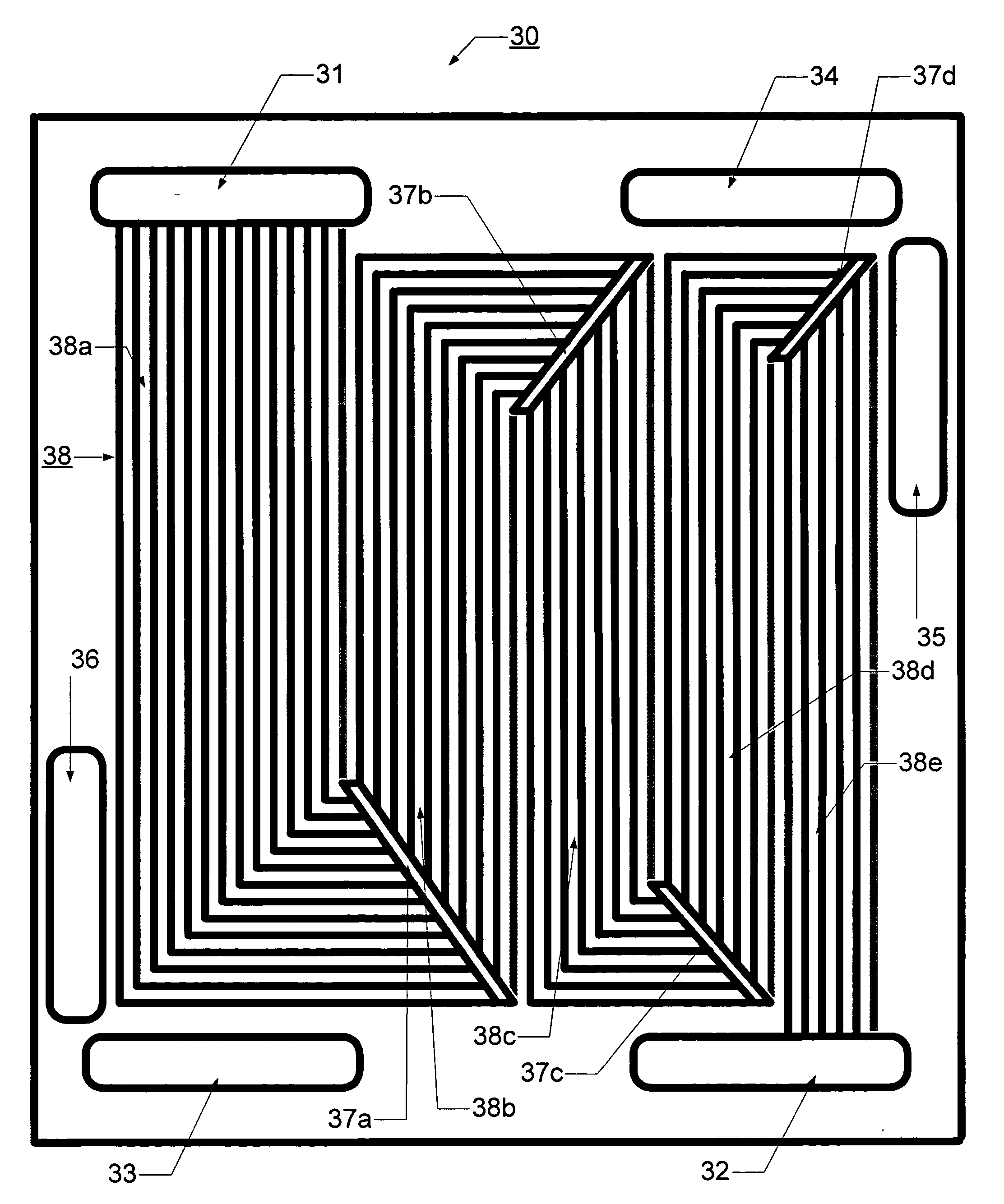
[0075]FIGS. 6 and 7 illustrate anode flow field plates 30, 40 according to a second and a third embodiment according to the present invention, in which the flow channels are provided in a fashion similar to the conventional serpentine pattern. Similarly to FIG. 4 these two figures show the flow field based on a “Constant Gas Flow Rate Approach” in which a hydrogen concentration of 70% and a hydrogen utilization of 80% are assumed. The flow channels 38, 48 are reduced as 14-10-8-7-6, for a total of 45 channels. Replacing the headers 17 in FIG. 1, several connecting and redistributing mechanisms 37, 47 are provided, which allow the flow channels 38, 48 to decrease from the number in a previous zone to the number of the following zone according to the determined decrease rate.

[0076]FIGS. 8 and 9 schematically show cathode flow field plates 50, 60 according to a second and third embodiment of the present invention, in which the flow channels 58, 68 are provided in a fashion similar to t...

fourth embodiment

[0078] Now, referring to FIG. 10 and to FIG. 11, there is shown the present invention, based on the approach of “Constant Molecules per Active Area”, which would maximize the utilization of the catalysts. The anode plate 70 of FIG. 10 is assumed to have a 70% hydrogen concentration and an 80% hydrogen utilization. The cathode plate 80 of FIG. 11 assumed an oxygen concentration of 21% and an oxygen utilization of 50%. Based on this approach, the number of grooves will decrease exponentially (equation (5)) to the number that equals the number on the inlet side multiplied by (1-η0). In the case of FIG. 10, the number of grooves decreases as 16-11-7-5-3, while in FIG. 11 it is 19-13-10, with both giving the same total of 42 channels. Compared to the approach of “Constant Gas Flow Rate”, the approach of “Constant Molecules per Active Area” leads to faster decrease in the number of flow channels or flow areas from the inlet toward the outlet. Therefore, the gas velocity would expect to in...


PUM

PropertyMeasurementUnit
temperatureaaaaaaaaaa
current densityaaaaaaaaaa

Abstract

A method of flowing reactants over an ion exchange membrane in a fuel cell flow field plate is provided. The flow field plate is provided, comprising a network of flow channels in the plate bounded by an electrochemically active electrode, the network comprising a series of passages having parallel grooves, the passages being interconnected by a header providing a substantially even redistribution of fluid flow received from grooves of one passage to grooves of the next passage. A reactant fluid is supplied to create a flow across the network to achieve a desired reactant utilization, wherein a flow rate and a concentration of reactant molecules per active area of membrane in the grooves increase by less than 80% across the header.

Description

CROSS-REFERENCE TO RELATED APPLICATIONS [0001] This is the first application filed for the present invention. STATEMENT REGARDING US GOVERNMENT SPONSORED RESEARCH OR DEVELOPMENT [0002] Not Applicable. FIELD OF THE INVENTION [0003] This invention relates to electrochemical fuel cells constructed of a single or multiple electrically conductive plates having inputs and outputs of fuel (e.g. hydrogen or reformate) and oxidant (e.g. O2 or air) and coolant if necessary. More particularly, the present invention relates to fluid flow field plates. BACKGROUND OF THE INVENTION [0004] A fuel cell is a device in which a fuel and an oxidizing agent are continuously and independently supplied to the anode and cathode electrodes, respectively, to undertake electrochemical reactions by which chemical energy is converted directly into electrical energy and by-product of heat. Fuel Cells are therefore inherently clean and efficient and are uniquely able to address the issues of environmental degradat...

Claims


Application Information

Patent Timeline
Patent Type & Authority Applications(United States)
IPC IPC(8): H01M8/00H01M8/02H01M8/04H01M8/10
CPCH01M8/0258H01M8/0267H01M8/2483H01M8/241H01M8/0263H01M8/1007H01M8/026Y02E60/50H01M8/02
Inventor BAI, DINGRONGCHOUINARD, JEAN-GUYELKAIM, DAVID
Owner HYTEON
Why Eureka
Try Eureka