Organic light-emitting device comprising buffer layer and method for fabricating the same
- Summary
- Abstract
- Description
- Claims
- Application Information
AI Technical Summary
Benefits of technology
Problems solved by technology
Method used
Image
Examples
examples 1-5
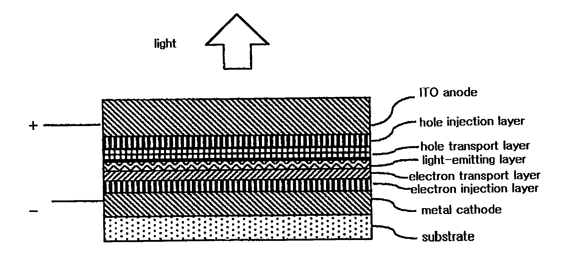
[0077] On a glass substrate, a cathode (Al) having a thickness of 150 nm and an electron injection layer (LiF) having a thickness of 1.5 nm were sequentially formed by a thermal evaporation process. Then, on the electron injection layer, an electron transport layer consisting of a thin film made of a material represented by the following formula 2-1 comprising imidazole group was formed to a thickness of 20 nm.
[0078] Then, on the electron transport layer, an Alq3 light-emitting host was co-deposited with C545T (10-(2-benzothiazolyl)-1,1,7,7-tetramethyl-2,3,6,7-tetrahyro-1H,5H,11H-1)benzopyrano[6,7,8-ij]quinolizin-11-one) to form a light-emitting layer having a thickness of 30 nm. On the light-emitting layer, a hole transport layer consisting of a thin film made of NPB (4,4′-bis[N-(1-napthyl)-N-phenylamino]biphenyl) was deposited to a thickness of 40 nm. On the hole transport layer, a hole injection / buffer layer made of a compound represented by the following formula 1-1 was formed...
example 6
[0080] A both-side emission type organic light-emitting device was fabricated in the same manner as described in Examples 1-5 except that a cathode consisting of an thin Al film having a very small thickness of 5 nm formed on an ITO film having a thickness of 150 nm is used in place of the cathode consisting of the thin Al film having a thickness of 150 nm.
[0081] [Measurement of Current-Voltage Characteristics and Light Emission Characteristics of Device]
[0082] To the organic light-emitting device fabricated in Example 1, each of reverse and forward electric fields was applied at a voltage increasing at increments of 0.2 volts while current at each voltage value was measured. The measurement results are shown in FIGS. 6 and 7, respectively. Also, to the organic light-emitting device fabricated in Example 1, current was applied while gradually increasing current density from 10 mA / cm2 to 100 mA / cm2, and at the same time, the luminous intensity of the device was measured using photom...
example 7
[0087] On a glass substrate, a cathode (Al) having a thickness of 150 nm and an electron injection layer (LiF) having a thickness of 1.5 nm were sequentially formed by a thermal evaporation process. Then, on the electron injection layer, an electron transport layer consisting of a thin film made of the material comprising imidazole group represented by the above formula 2-1 was formed to a thickness of 150 nm. On the electron transport layer, an electron injection layer (LiF) having a thickness of 1.5 nm and Al layer having a thickness of 150 nm were formed sequentially to fabricate a symmetrical-type device as shown in FIG. 13 in which electric current runs only through electrons.
PUM
 Abstract
Description
Claims
Application Information
 - R&D
- Intellectual Property
- Life Sciences
- Materials
- Tech Scout
- Unparalleled Data Quality
- Higher Quality Content
- 60% Fewer Hallucinations
Browse by: Latest US Patents, China's latest patents, Technical Efficacy Thesaurus, Application Domain, Technology Topic, Popular Technical Reports.
© 2025 PatSnap. All rights reserved.Legal|Privacy policy|Modern Slavery Act Transparency Statement|Sitemap|About US| Contact US: help@patsnap.com


