Thermally stable diamond polycrystalline diamond constructions

a polycrystalline diamond and polycrystalline technology, applied in the field of polycrystalline diamond materials, can solve the problems of pcd structure, unsuitable for further use, and vulnerability to thermal degradation, and achieve the effect of facilitating attachment and improving the degree of thermal stability

Active Publication Date: 2006-03-23
SMITH INT INC
View PDF99 Cites 184 Cited by
  • Summary
  • Abstract
  • Description
  • Claims
  • Application Information

AI Technical Summary

Benefits of technology

[0020] Thermally stable constructions of this invention display an enhanced degree of thermal stability when compared to conventional PCD materials, and include a substrate material bonded to the PCD body that facilitates attachment therewith to an application device by conventional method such as welding or brazing and the like.

Problems solved by technology

A problem known to exist with such conventional PCD materials is that they are vulnerable to thermal degradation, when exposed to elevated temperature cutting and / or wear applications, caused by the differential that exists between the thermal expansion characteristics of the interstitial solvent metal catalyst material and the thermal expansion characteristics of the intercrystalline bonded diamond.
Such differential thermal expansion is known to occur at temperatures of about 400° C., can cause ruptures to occur in the diamond-to-diamond bonding, and eventually result in the formation of cracks and chips in the PCD structure, rendering the PCD structure unsuited for further use.
Specifically, the solvent metal catalyst is known to cause an undesired catalyzed phase transformation in diamond (converting it to carbon monoxide, carbon dioxide, or graphite) with increasing temperature, thereby limiting practical use of the PCD material to about 750° C.
While this approach produces an entire PCD body that is substantially free of the solvent catalyst material, is it fairly time consuming.
Additionally, a problem known to exist with this approach is that the lack of solvent metal catalyst within the PCD body precludes the subsequent attachment of a metallic substrate to the PCD body by solvent catalyst infiltration.
However, the difference in thermal expansion between the thermally stable PCD body and the substrate, and the poor wetability of the thermally stable PCD body diamond surface due to the substantial absence of solvent metal catalyst, makes it very difficult to bond the thermally stable PCD body to conventionally used substrates.
Since such PCD bodies, rendered thermally stable by having the catalyzing material removed from the entire diamond body, are devoid of a metallic substrate they cannot (e.g., when configured for use as a drill bit cutter) be attached to a drill bit by conventional brazing process.
The use of such thermally stable PCD body in this particular application necessitates that the PCD body itself be mounted to the drill bit by mechanical or interference fit during manufacturing of the drill bit, which is labor intensive, time consuming, and does not provide a most secure method of attachment.

Method used


Image

  • Thermally stable diamond polycrystalline diamond constructions
  • Thermally stable diamond polycrystalline diamond constructions
  • Thermally stable diamond polycrystalline diamond constructions

Examples


example 1

TSPCD Construction

[0082] Synthetic diamond powder having an average grain size of approximately 20 micrometers was mixed together for a period of approximately 1 hour by conventional process. The resulting mixture included approximately six percent by volume cobalt solvent metal catalyst, and WC—Co based on the total volume of the mixture, and was cleaned. The mixture was loaded into a refractory metal container with a cemented tungsten carbide substrate and the container was surrounded by pressed salt (NaCl) and this arrangement was placed within a graphite heating element. This graphite heating element containing the pressed salt and the diamond powder / substrate encapsulated in the refractory container was then loaded in a vessel made of a high-temperature / high-pressure self-sealing powdered ceramic material formed by cold pressing into a suitable shape. The self-sealing powdered ceramic vessel was placed in a hydraulic press having one or more rams that press anvils into a centr...

example 2

TSPCD Construction

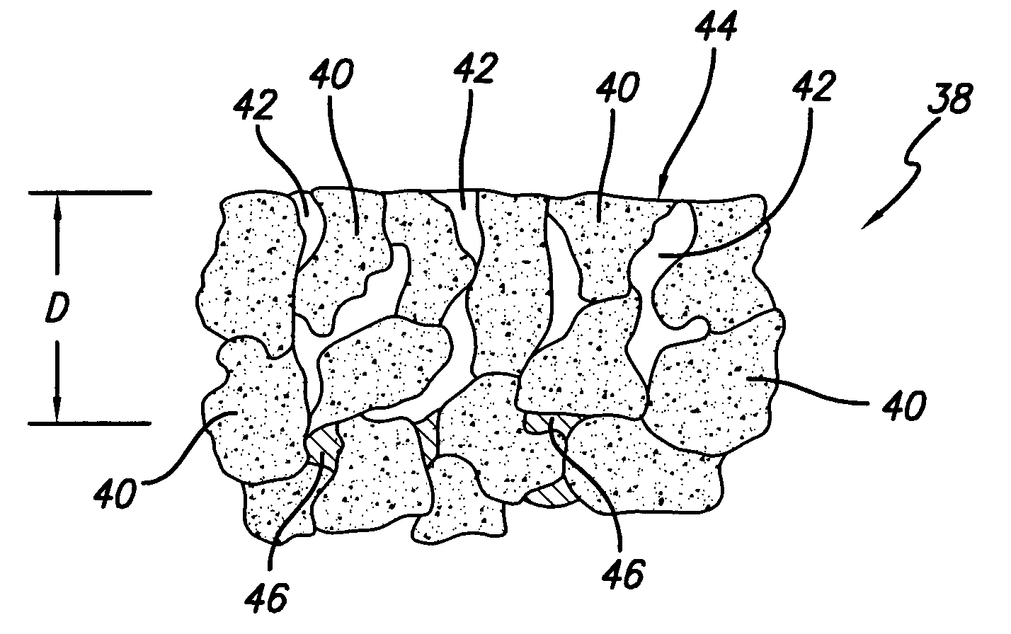
[0088] A TSPCD construction of this invention was prepared according to the process described above for example 1 except that the treatment for providing a thermally stable region in the PCD body was conducted for longer period of time. Specifically, the PCD compact was immersed on the leaching agent for a period of approximately 300 minutes. After the designated treatment time had passed, the PCD compact and fixture assembly was removed from the leaching agent and PCD compact was removed from the protective fixture. The resulting TSPCD construction formed according to this example had a thermally stable region that extended from the working surfaces a distance into the diamond body of approximately 0.075 mm.

[0089] A feature of TSPCD constructions of this invention is that they include a defined thermally stable region within a PCD body that provides an improved degree of wear and abrasion resistance, when compared to conventional PCD, while at the same time prov...


PUM

PropertyMeasurementUnit
depthaaaaaaaaaa
depthaaaaaaaaaa
depthaaaaaaaaaa

Abstract

Thermally stable diamond constructions comprise a diamond body having a plurality of bonded diamond crystals, a plurality of interstitial regions disposed among the crystals, and a substrate attached to the body. The body includes a working surface and a side surface extending away from the working surface to the substrate. The body comprises a first region adjacent the side surface that is substantially free of a catalyst material and that extends a partial depth into the diamond body. The first region can further extend to at least a portion of the working surface and a partial depth therefrom into the diamond body. The diamond body can be formed from natural diamond grains and/or a mixture of natural and synthetic diamond grains. A surface of the diamond body is treated to provide the first region, and before treatment is finished to an approximate final dimension.

Description

RELATION TO COPENDING PATENT APPLICATION [0001] This patent application is a continuation-in-part of U.S. patent application Ser. No. 10 / 947,075 filed on Sep. 21, 2004, which is incorporated herein by reference.FIELD OF THE INVENTION [0002] This invention generally relates to polycrystalline diamond materials and, more specifically, to polycrystalline diamond materials that have been specifically engineered to provide an improved degree of thermal stability when compared to conventional polycrystalline diamond materials, thereby providing an improved degree of service life in desired cutting and / or drilling applications. BACKGROUND OF THE INVENTION [0003] Polycrystalline diamond (PCD) materials and PCD elements formed therefrom are well known in the art. Conventional PCD is formed by combining synthetic diamond grains with a suitable solvent catalyst material to form a mixture. The mixture is subjected to processing conditions of extremely high pressure / high temperature, where the s...

Claims


Application Information

Patent Timeline
Patent Type & Authority Applications(United States)
IPC IPC(8): E21B10/36
CPCB22F2003/244B22F2005/001B22F2998/00C22C26/00E21B10/567Y10T407/27Y10T428/30B24D3/10Y10T428/24488Y10T428/26Y10T428/24612B22F2207/03Y10T428/31678
Inventor EYRE, RONALD K.
Owner SMITH INT INC
Why Eureka
Try Eureka