
Optical information recording medium

a technology of optical information and recording medium, which is applied in the direction of instruments, photomechanical equipment, thermography, etc., can solve the problems of insufficient recording capacity to cope with future needs, unsatisfactory storage stability of disks, and the inability to produce optical disks using dyes with this production method including coating, etc., to achieve excellent recording characteristics, improve dye solubility, coatability, and the effect of drying load

Inactive Publication Date: 2006-03-30
FUJIFILM HLDG CORP +1
View PDF6 Cites 8 Cited by
  • Summary
  • Abstract
  • Description
  • Claims
  • Application Information

AI Technical Summary

Benefits of technology

[0016] The inventors of the present invention have found that the above demand can be met by using a dye which has a specific structure and have completed the invention. Specifically, the inventors have made earnest studies. As a result, the inventors have found that a dye in which a UV absorbing dye which has low solubility and which absorbs light having a wavelength of 280 nm to 450 nm and a dye which absorbs light having a wavelength of 450 nm to 900 nm are bonded to each other with a covalent bond has improved solubility and can form a uniform dye film without local generation of crystals. Also, the inventors have found that the dye has improved fastness to light, humidity and temperature.
[0019] The invention can provide an optical information recording medium in which information can be recorded at high density and from which the information can be reproduced by irradiating laser light, particularly laser light having a wavelength of 450 nm or less and which has excellent recording characteristics.
[0021] Further, the invention can provide an optical information recording medium having improved dye solubility, coatability, and drying load which are problematic when producing disks.

Problems solved by technology

The DVD-R satisfies the demand for a large capacity recording medium to some extent, however, it does not have enough recording capacity to cope with future needs.
This is due to the fact that these disks do not reach the level at which recording characteristics such as reflectance and degree of modulation are satisfactory and also, these disks have unsatisfactory storage stability.
However, when the dye used for an optical disk has insufficient solubility or dissolution stability in the solvent, it is impossible to produce an optical disk using the dye with this production method including coating.
Also, this method has problems concerning the coatability of the dye and drying load when producing an optical disk.
However, many such dyes have a low molar extinction coefficient and low solubility in a solvent for coating solutions, and none of these dyes satisfy requirements for optical disks.
If the structure of the dye is modified to introduce a substituent improving volubility in a dye molecule, the molecular weight of the dye increases, which resultantly drops the refractive index of the dye film.
Conventionally, it is difficult to satisfy the demand for both high solubility and high refractive index.
Also, many dyes having absorption in the ultraviolet region have low fastness to light, humidity, temperature and atmosphere.

Method used


Image

  • Optical information recording medium
  • Optical information recording medium
  • Optical information recording medium

Examples


example 1

Evaluation of Optical Disk (Optical Information Recording Medium)

[0137] A substrate having a thickness of 1.1 mm was made from a polycarbonate resin (Panlight AD5503) manufactured by Teijin Chemicals Ltd. by injection molding. The track pitch of grooves on the substrate was 320 nm, the half width of the portions on the grooves was 110 nm and the depth of the grooves was 35 nm.

[0138] A reflecting layer having a thickness of 100 nm was formed on the substrate by using a target containing Ag (98.1 parts), Pd (0.9 parts) and Cu (1.0 part) by a vacuum filming method.

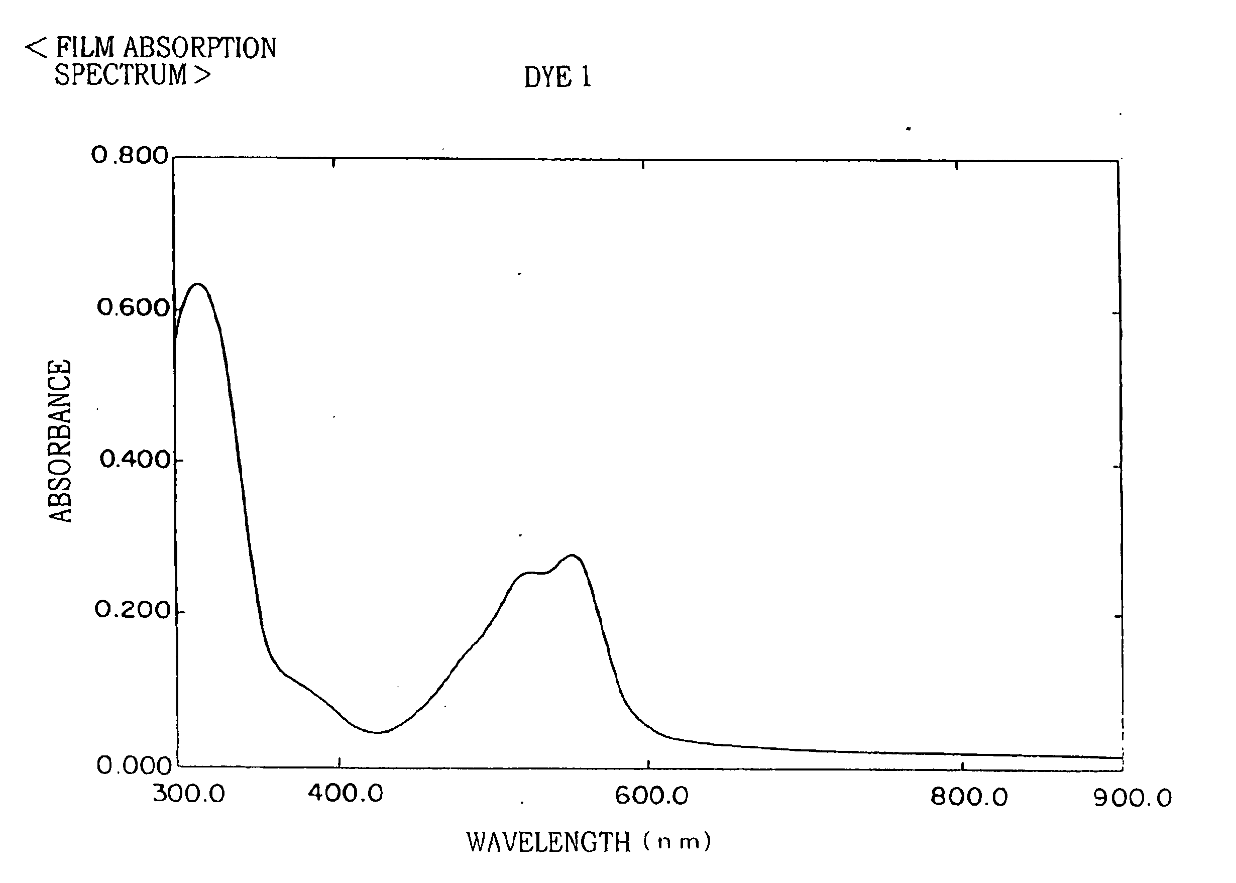
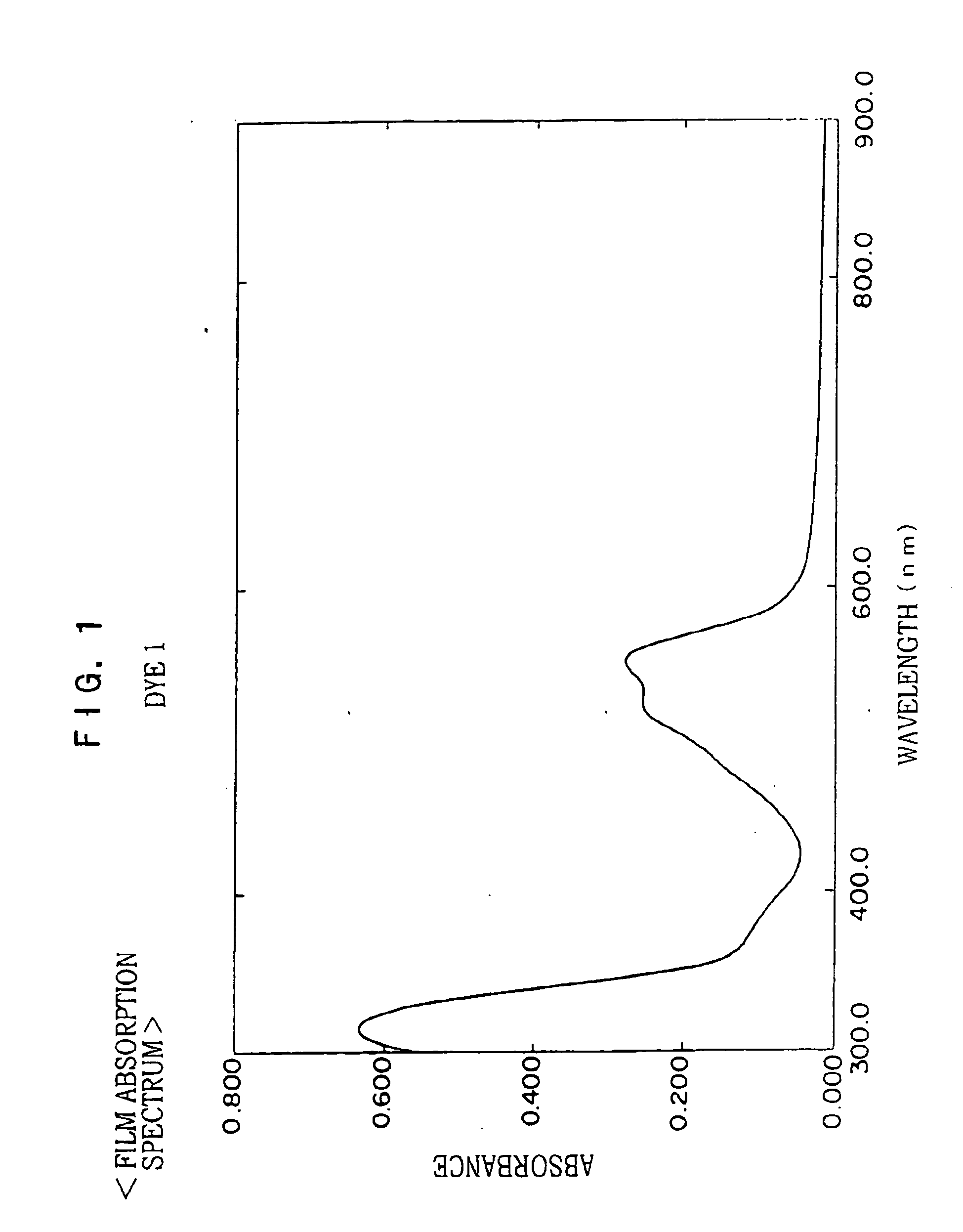
[0139] Next, dye 1 was weighed such that the amount of the dye was 2.5 g with respect to 100 ml of TFP and the weighed dye 1 was mixed with TFP. Ultrasonic wave was applied onto the resultant mixture for 2 hours to dissolve the dye in the solvent and then the resultant solution was allowed to stand under an environment of 23° C. and 50% humidity for at least 0.5 hours. Then, the solution was filtered with a filter having ...

examples 2 to 11

, and Comparative Examples 1 to 6

[0143] Optical information recording media of Examples 2 to 11 and Comparative Examples 1, 3, 5 and 6 were manufactured or attempts to manufacture optical information recording media of Comparative Examples 2 and 4 were conducted and evaluated in the same manner as in Example 1 except that dyes described in Table 2 were used in place of dye 1 of Example 1, respectively.

Comparative Dye B

Comparative Dye C

Comparative Dye D

(Compound 1-1 Described in JP-A No. 2001-253171)

Comparative Dye E

(Dye (12) Described in JP-A No. 2002-2117)

Comparative Dye F

(Dye (1-1) Described in JP-A No. 2002-301870)

Evaluation of Light Fastness

[0144] A light-fading test was conducted for the manufactured optical information recording media by using a 100000 Lux Merry-go-round type light-fading tester. The optical information recording medium was irradiated with light for 3 days without using a UV filter. The residual rate was obtained from the transmission c...


PUM

PropertyMeasurementUnit
Nanoscale particle sizeaaaaaaaaaa

Abstract

The present invention provides an optical information recording medium comprising a substrate having provided thereon a recording layer in which information can be recorded by laser light irradiation, wherein the recording layer contains a dye represented by the following formula (I): Formula (I) wherein Dye represents a dye residue having an absorption as high as 10000 (cm−1·mol−1) or more as a molar extinction coefficient for light having a wavelength of 450 nm to 900 nm; L represents a divalent connecting group or a single bond; UV represents a dye residue having an absorption as high as 10000 (cm−1·mol−1) or more as a molar extinction coefficient for light having a wavelength of 280 nm to 450 nm; and m denotes an integer from 1 to 8.

Description

CROSS-REFERENCE TO RELATED APPLICATION [0001] This application claims priority under 35 USC 119 from Japanese Patent Application No. 2003-275125, the disclosure of which is incorporated by reference herein. BACKGROUND OF THE INVENTION [0002] 1. Field of the Invention [0003] The present invention relates to an optical information recording medium, which can record and reproduce information by using laser light. The invention particularly relates to a heat-mode type optical information recording medium which contains an azo dye having a specific structure and is suitable for recording information with laser light. [0004] 2. Description of the Related Art [0005] Optical information recording media (optical disks) capable of recording information only once with laser light have been known. These optical disks are also called write-once CDs (so-called CD-Rs) and are typically structured to have a recording layer made of an organic dye, a light reflecting layer made of a metal such as gol...

Claims


Application Information

Patent Timeline
IPC IPC(8): G11B7/24B41M5/26C09B33/18C09B47/24C09B47/26C09B56/04C09B56/16G11B7/244G11B7/246G11B7/247
CPCG11B7/245G11B2007/25716G11B7/2467G11B7/247G11B7/2472G11B7/2475G11B7/2478G11B7/248G11B7/249G11B7/2531G11B7/2533G11B7/2534G11B7/2535G11B7/256G11B7/259G11B2007/25706G11B2007/2571G11B2007/25715G11B7/246
Inventor MIKOSHIBA, HISASHIWATANABE, TETSUYAKATAYAMA, KAZUTOSHI
Owner FUJIFILM HLDG CORP
Learn More