Aneurysm treatment using semi-compliant balloon

aneurysm treatment and semi-compliant technology, applied in the field of aneurysm treatment using semi-compliant balloons, can solve the problems of small ruptures that cannot be effectively reconstructed, aneurysms that are out of the normal artery path, and bleeding into the space between the brain and the arachnoid membrane, so as to achieve simplified deployment procedures

Inactive Publication Date: 2006-04-13
BOARD OF REGENTS THE LELAND STANFORD JR UNIV THE
View PDF11 Cites 84 Cited by
  • Summary
  • Abstract
  • Description
  • Claims
  • Application Information

AI Technical Summary

Benefits of technology

[0138] 5. Medical device deployment should not be too complex. This is because the deployment mechanism sh...

Problems solved by technology

Thus small ruptures continue to form and be repaired without any effective restructuring, and an aneurysm forms out from the normal artery path.
Rupture of an aneurysm results in bleeding into the space between the brain and the arachnoid membrane that surrounds it.
SAH also causes a rapid increase in intracranial pressure, which in turn may cause global ischemia, brain hemorrhage, or other disruption of more fragile structures in the brain stem.
Cigarette smoking and excess alcohol consumption are known to increase the chance of rupture.
One major limitation of endovascular coiling is that it is insufficient in treating wide neck intracranial aneurysms.
The problem is that as coils are expelled into the aneurysm they can be washed out by the higher flows that are present with a wider neck.
At some point, the tear grows too large for self repair, and rupture occurs in direct result of fluid pressure-induced wall stress.
There is currently not a widely accepted effective endovascular device for occluding wide neck aneurysms.
Traditional coiling procedures carry an estimated cost of $16,000.
Additionally, as diagnostic capabilities improve these previous statistics may become irrelevant as it will become more common to treat unruptured aneurysms when there is less surgical risk involved.
This becomes even more of an issue if a detached section of catheter is also hanging from the portion of the balloon that is proximal to the operator.
Any structure protruding into the main flow of the parent artery may increase the occurrence of a thrombus or other occlusions.
However, a compliant balloon ma...

Method used


Image

  • Aneurysm treatment using semi-compliant balloon
  • Aneurysm treatment using semi-compliant balloon
  • Aneurysm treatment using semi-compliant balloon

Examples


example i

Aneurysm Cast Making for Testing Balloon

Blow Molding

[0153] In order to create our in vitro test platform for the deployment of our device, we utilized a blow molding process. Using this blow molding process, we were able to create soft, compliant models of the aneurysm.

[0154] The basic idea behind this blow molding process is to first heat a section of vinyl tubing until soft, and then introduce compressed air into the tubing to expand and permanently deform the shape. If the tubing is constrained within a TEFLON mold, the tubing will expand to the form of the mold when compressed air is introduced.

[0155] The tubing can be heated one of two ways: through direct heating of the outer tubing surface or heating through the interior pathway. Points exposed to greater heat will expand more than its surrounding area, therefore, direct heating of the outer surface can be used to make arbitrary shapes by manipulating the localized heating of the tubing. On the other hand, while heating ...

example ii

Balloon Manufacture

[0163] A urethane balloon of 12 mm diameter was made through blow molding or vacuum forming with appropriate glass casts while the double lumen catheter was manufactured by extrusion of clear PEBAX resins through an extrusion machine. However, the test device was assembled manually.

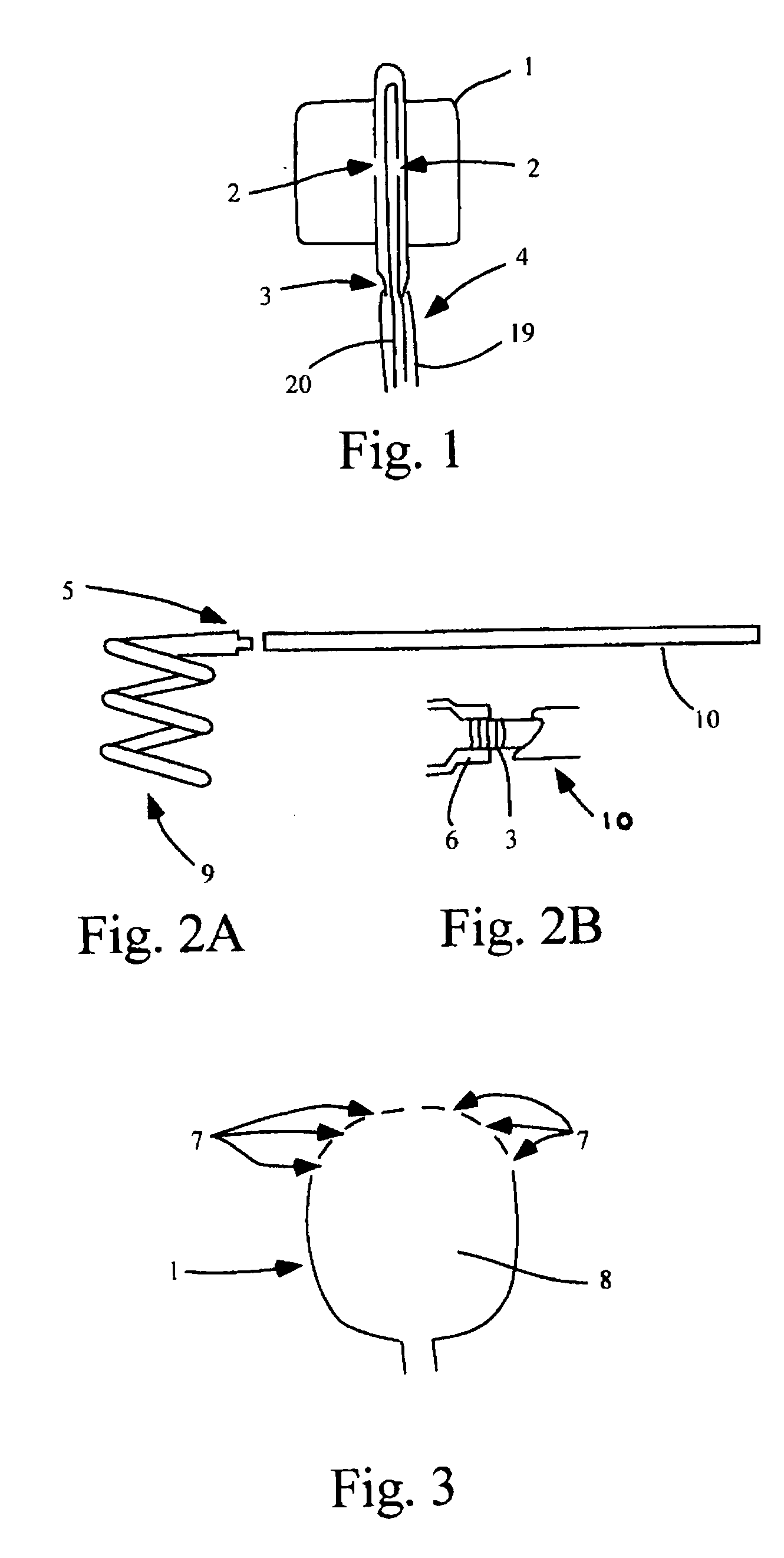
[0164] Flourinated ethylene propylene (FEP) heat shrink tubing was used to bond the urethane balloon to the double lumen catheter. When heat was applied to the tubing, the shrinking of the tubing as well as the thermal molecular compatibility of the urethane and PEBAX allowed a strong bond to form between the two materials. The test device consisted of a double lumen catheter with a detachable distal section adjoined via a stainless steel coupling to the rest of the catheter (see FIG. 13). Hence, the assembly of the device could be separated into two portions as follows.

Detachable Distal End

[0165] The distal end was manufactured as follows:

[0166] 1. The collars of the urethane bal...

example iii

In Vitro Testing

(i) Test Setup

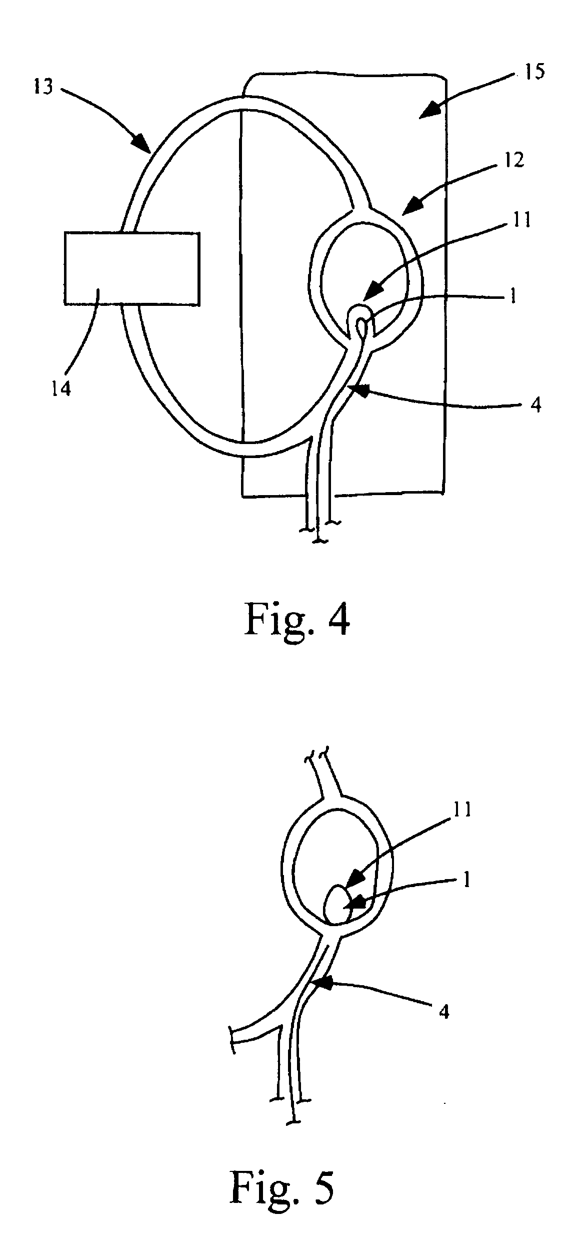
[0180] In vitro tests for proof-of-concept devices were performed for prototypes of scale 5× and 2×. The setup for the in vitro test is shown in FIG. 4. Tests were performed in simplified intracranial vasculature phantoms manufactured to corresponding scales from heat-treated PVC tubing as describe in Example I.

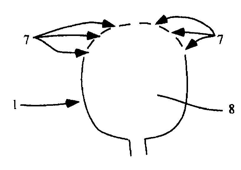
[0181] The model vasculature in FIG. 4 consists of a simplified Circle of Willis replica (12) with a wide neck aneurysm at the bifurcation of the basilar artery (11). The vasculature phantom was placed in a water bath (15) of phosphate buffered saline solution mimicking the pH and electrical properties of blood. Hemodynamic conditions were simulated by driving a pulsatile-flow with a Harvard pump (14). As shown, the test circuit includes the phantom vasculature and the bath. An entry point in the vasculature phantom allows the test device to be inserted and delivered to the aneurysm site.

(ii) In Vitro Test at 5× Scale

[0182] In the 5× scale...


PUM


Abstract

A device for occluding an aneurysm comprising: a detachable, semi-compliant, radially-expanding balloon mounted on a catheter, wherein the balloon is in fluid communication with the catheter, wherein the balloon comprises a plurality of micropores, and wherein the micropores in the balloon allow expression of a bio-adhesive fluid at a defined pressure from the inside to the outside of the balloon.

Description

[0001] The present application claims priority to U.S. Provisional Patent Application Ser. No. 60 / 600,074 entitled “Aneurysm Treatment Using Semi-Compliant Balloon”, filed Aug. 9, 2004, which is herein incorporated by reference in its entirety for all purposes.BACKGROUND Intracranial Aneurysms [0002] An aneurysm is an out-pouching or dilatation of a blood vessel within the body. It is generally believed that the aneurysm develops from an initial small lesion in the vessel wall. While there are many different stimuli proposed for this lesion, such as mechanical tearing due to highly concentrated wall stress or immune dysfunction, the propagation of the aneurysm from a small tear to a large dilatation is generally understood. Physiology of Aneurysms [0003] Arterial walls are constructed from three distinct layers. The innermost layer, adjacent to the lumen where blood flows, is called the intima. It is composed mostly of flat endothelial cells that regulate the majority of the funct...

Claims


Application Information

Patent Timeline
IPC IPC(8): A61M29/00
CPCA61B17/00491A61B17/12113A61B17/12136A61B17/12186A61B17/12195A61B2017/12063A61M25/10A61M2025/105A61M2025/1052A61M2025/1086
Inventor CHHABRA, MANIKHEKMAT, NEEMAJOHNSON, PETERLEE, AMYYAP, LIPKONG
Owner BOARD OF REGENTS THE LELAND STANFORD JR UNIV THE
Why Eureka
Try Eureka